140 MS-9600LS Series Manual — P/N 52646:B8 11/20/2015
Operating Instructions Read Status
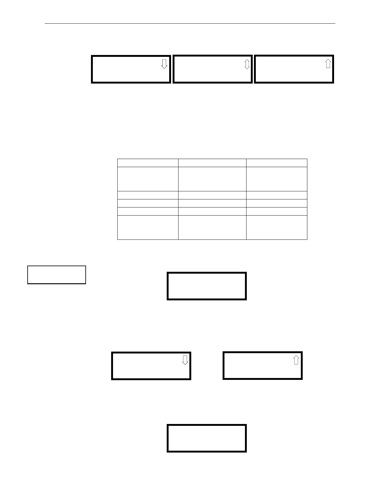
4.23.3 Power
Pressing 3 while viewing Read Status Screen #1 will display the following screens:
A real-time display of control panel voltages can be used to determine if system problems exist.
Note that Zones Screen #3 will only be displayed if the NACKEY NAC option card is installed, in
JP8 of the main circuit board, for Class B operation.
The following table lists the circuit being measured, possible conditions and their respective volt-
age ranges:
4.23.4 Trouble Reminder
Pressing 1 while viewing Read Status Screen #2 will display the following screen:
The screen indicates whether the Trouble Reminder feature is On or Off.
4.23.5 Timers
Pressing 2 while viewing Read Status Screen #2 will cause the following Timer screens to be dis-
played:
These screens indicate the delay time, in seconds, for each of four possible delay options.
4.23.6 NAC
Pressing 3 while viewing Read Status Screen #2 will display the following screen:
Circuit Condition Voltage Range
Battery
Normal Battery (nominal) 27.05 to 28.15 VDC
Low Battery 20.0 to 20.8 VDC
No Battery 0 to 18.36 VDC
24V Resettable Normal 21.25 to 27.50 VDC
24V Nonresettable Normal 21.25 to 27.50 VDC
Charger Normal 27.05 to 28.15 VDC
NACs
Normal -1.3 to -1.6 VDC
Open Circuit -2.3 to -2.5 VDC
Short Circuit 0 to 1.0 VDC
POWER
BATTERY 27.21V
24 V RST 25.31V
Zones Screen #1
POWER
CHARGER 28.36V
NAC 1 -2.39V
NAC 2 -2.39V
Zones Screen #2
POWER
NAC 3 -2.39V
NAC 4 -2.39V
Zones Screen #3
READ STATUS
1=TROUBLE REMINDER
2=TIMERS
3=NACS
Read Status Screen #2
TROUBLE REMINDER
TROUBLE REM ON
TIMERS
PAS DELAY 000
PRE SIGNAL 000
WATERFLOW 000
TIMERS
AC LOSS DELAY 4
NAC
1=NAC 1 3=NAC 3
2=NAC 2 4=NAC 4