Instruction Manual
D103409X012
Field Communicator Menu Trees
May 2013
130
Dynamic Response
1 SP Rate Open
2 SP Rate Close
3 View/Edit Lag Time
3 Lead/Lag
Hot Key
1 Instrument Mode
2 Control Mode
3 Protection
4 Stabilize/Optimize
Notes:
1‐1‐1 indicates fast‐key sequence to reach menu
This menu is available by pressing the left
arrow key from the previous menu.
Instrument level AD, PD, and ODV only.
Instrument level ODV only.
Instrument level HC, AD, and PD only.
Instrument level HC only.
Fast key sequence for Alert Record with instrument level ODV is 1‐2‐3‐7.
1‐1
1
1
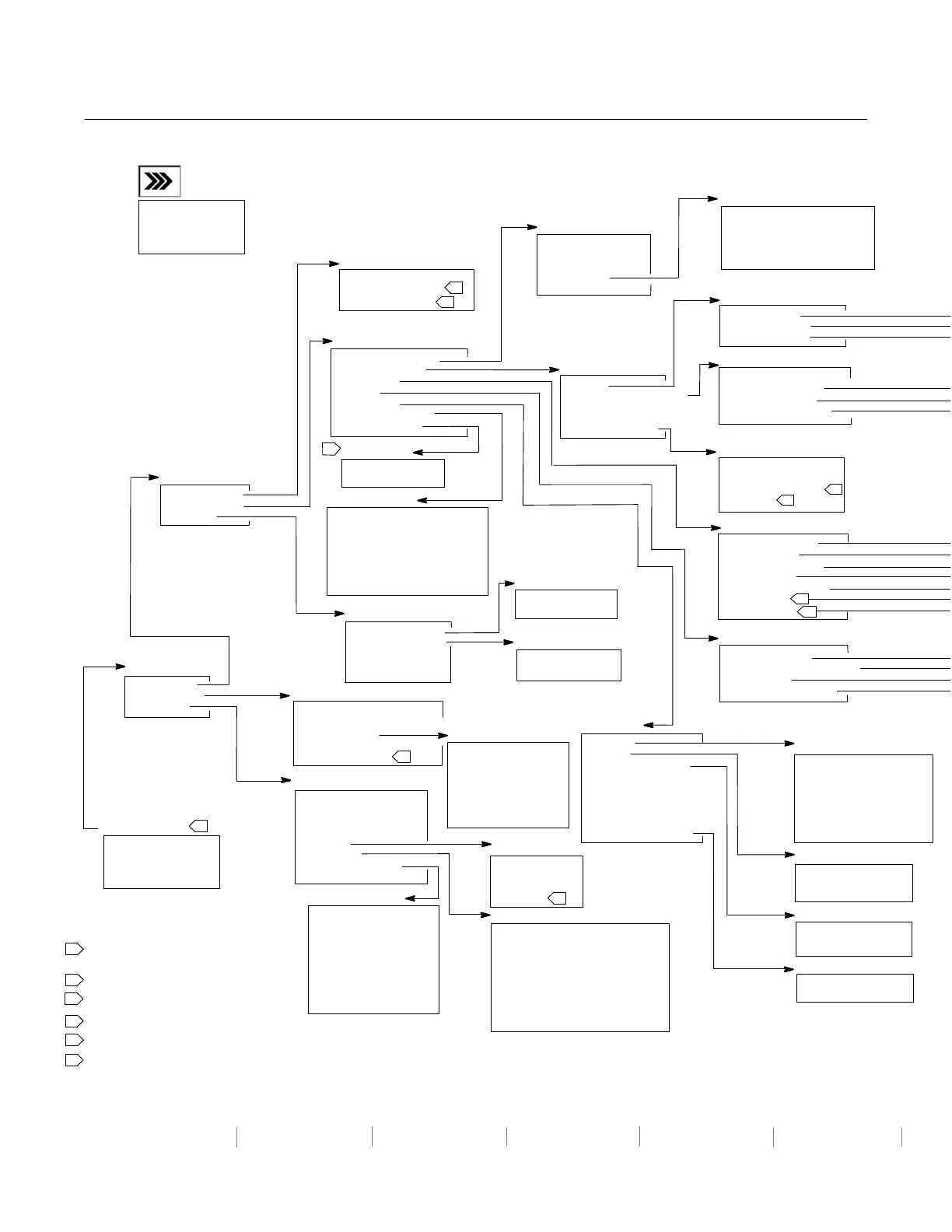
Field Communicator Menu Tree for
Instrument Level HC, AD, PD, and ODV
1
1‐2‐1
1‐2
1‐2‐4
1‐2‐1‐4
1‐2‐5
1‐2‐6
1‐3
1‐3‐1
1‐3‐2
2
3‐5
3‐6
1
2345
6
2
3
4
4
5
2
2‐3
1‐2‐7
1‐2‐3
3‐7
3
3
1‐2‐2
1‐2‐5‐2
1‐2‐5‐3
5
6
1‐2‐2‐1
1‐2‐2‐2
1‐2‐2‐5
2
1‐2‐5‐9
1‐2‐5‐1
Guided Setup
1 Setup Wizard
2 Performance Tuner
2 Stabilize/Optimize
Detailed Setup
1 Mode and Protection
2 Response Control
3 Alert Setup
4 Status
5 Instrument
6 Valve and Actuator
7 SIS/Partial Stroke
Online
1 Configure
2 Service Tools
3 Overview
Configure
1 Guided Setup
2 Detailed Setup
3 Calibrate
HART Application
1 Offline
2 Online
3 Utility
4 HART Diagnostics
Calibrate
1 Travel Calibration
2 Sensor Calibration
3 Relay Adjust
4 Restore Factory
4 Settings
Partial Stroke
1 PST Enable
2 PST Vars View/Edit
Burst Mode
1 Burst Enable
2 Change Burst Enable
3 Burst Command
4 Change Burst Command
5 Cmd 3 Configured Pressure
Mode and Protection
1 Instrument Mode
2 Control Mode
3 Restart Control Mode
4 Burst Mode
5 Protection
Device Information
1 HART Tag
2 Device ID
3 Manufacturer
4 Model
5 Device Revision
6 Firmware Revision
7 Hardware Revision
8 Instrument Level
9 HART Universal Revision
Variables
1 Auxiliary Input
2 Temperature
3 Maximum Recorded Temperature
4 Minimum Recorded Temperature
5 Cycle Counter
6 Travel Accumulator
7 Raw Travel Input
8 View Number of Days Powered Up
9 Number of Power Ups
Pressure
1 Pressure A
2 Pressure B
3 A minus B
4 Supply
Service Tools
1 Alert Conditions
2 Status
3 Device Record
4 Stroke Valve
5 Partial Stroke Test
Overview
1 Analog In
2 Setpoint
3 Travel
4 Drive Signal
5 Pressure
6 Variables
7 Device Information
8 DD Information
Device Record
1 Maximum Recorded
Temperature
2 Minimum Recorded
Temperature
3 View Number of Days
Powered Up
4 Number of Power Ups
Response Control
1 Tuning
2 Travel/Pressure Control
3 Input Characterization
4 Custom Characterization Table
5 Dynamic Response
Travel Calibration
1 Auto Calibration
2 Manual Calibration
Sensor Calibration
1 Pressure Sensors
2 Analog In Calib
Alert Setup
1 Electronics Alerts
2 Sensor Alerts
3 Environment Alerts
4 Travel Alerts
5 Travel History Alerts
6 SIS Alerts
6 Alert Record
Valve and Actuator
1 Manufacturer
2 Valve Serial Number
3 Valve Style
4 Actuator Style
5 Travel Sensor Motion
6 View/ Edit Feedback Connection
7 Assembly Specification Sheet
Tuning
1 Travel Tuning
2 Integral Settings
3 Pressure Tuning
Travel/Pressure Control
1 Travel/Pressure Select
2 Cutoffs and Limits
3 Pressure Control
4 End Pt Press Control
Instrument
1 General
2 Units
3 Analog Input Range
4 Relay Type
5 Zero Power Condition
6 Maximum Supply Pressure
7 Auxiliary Terminal Action
8 Instrument Date and Time
9 Calib Status and Type
Status
1 Instrument Time
2 Calibration and Diagnostics
3 Operational
4 Integrator Saturation
Units
1 Pressure Units
2 Temperature Units
3 Analog In Units
Analog Input Range
1 Input Range Hi
2 Input Range Lo
Calib Status and Type
1 Last AutoCal Status
2 Last Calibration Type
General
1 HART Tag
2 Message
3 Descriptor
4 Date
5 Valve Serial Number
6 Instrument Serial Number
7 Polling Address
3
6
3
3
 Loading...


