Instruction Manual
D103409X012
Detailed Setup
May 2013
65
D Travel Limit Lo—Defines the low limit for the travel in percent (%) of ranged travel. It is the minimum allowable travel
(in percent of ranged travel) for the valve. During operation, the travel target will not exceed this limit. When a
Travel Limit Low is set, the Travel Cutoff Low is deactivated, since only one of these parameters can be active. Travel
Limit Low is deactivated by setting it to -25.0%.
D Change Travel Limits— Allows you to set hi and lo travel limits. Setting a travel limit will eliminate the corresponding
Tvl/Press Cutoff.
Travel History Alerts
Field Communicator Configure > Detailed Setup > Alerts > Travel History Alerts (1‐2‐3‐5)
Cycle Counter
D Cycle Count Alert Enable—Yes or No. Activates checking of the difference between the Cycle Counter and the Cycle
Counter Alert point. The Cycle Counter Alert is set when the value exceeds the Cycle Counter Alert point. It is
cleared after you reset the Cycle Counter to a value less than the alert point. Factory default is No.
D Cycle Counter—Records the number of times the travel changes direction. The change in direction must occur after
the deadband has been exceeded before it can be counted as a cycle. See figure 4‐3. You can reset the Cycle
Counter by configuring it as zero.
D Cycle Count Alert Point—The value of the Cycle Counter, in cycles, which, when exceeded, sets the Cycle Counter
Alert.
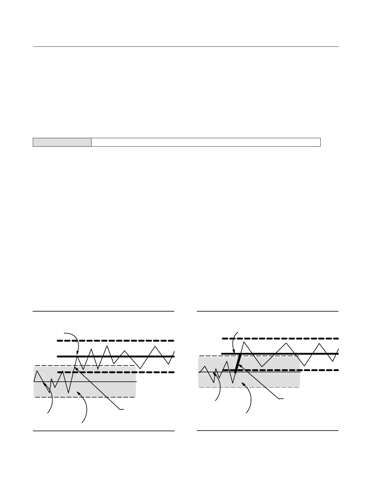
Cycle Count/Travel Accumulator Deadband
D Deadband—Cycle Counter Deadband is the area around the travel reference point, in percent (%) of ranged travel,
that was established at the last increment of the Cycle Counter. This area must be exceeded before a change in
travel direction can be counted as a cycle. See figure 4‐3.
Travel Accumulator Deadband is the area around the travel reference point, in percent (%) of ranged travel, that was
established at the last increment of the accumulator. This area must be exceeded before a change in travel can be
accumulated. See figure 4‐4.
Table 4‐3. Cycle Counter Deadband (set at 10%)
Deadband Reference
Deadband (+/- 5%)
Deadband exceeded, and direction
changed, new Reference Point
established
Point
Point at which
cycle is counted
A6533‐1/IL
Figure 4‐4. Travel Accumulator Deadband (set at
10%)
Deadband Reference
Deadband (+/- 5%)
Deadband exceeded,
new Reference Point established
Point
This amount of change is
added to the Travel
Accumulator
A6534/IL
 Loading...


