Instruction Manual
D103409X012
Installation
May 2013
29
Double‐Acting Actuators
DVC6200 digital valve controllers on double‐acting actuators always use relay A. With no input current, OUTPUT A is at
0 pressure and OUTPUT B is at full supply pressure when the relay is properly adjusted. To have the actuator stem
extend from the cylinder with increasing input signal, connect OUTPUT A to the upper actuator cylinder connection.
Connect OUTPUT B to the lower cylinder connection. To have the actuator stem retract into the cylinder with
increasing input signal, connect OUTPUT A to the lower actuator cylinder connection. Connect OUTPUT B to the upper
cylinder connection.
Special Construction to Support Solenoid Valve Testing
Note
Solenoid valve testing is only available for instrument level ODV.
In single‐acting actuator applications with a solenoid valve installed, the DVC6200 can be configured to test the
operation of the solenoid valve. This is accomplished by connecting the “unused” output port from the DVC6200 to
the pneumatic line between the solenoid valve and the actuator, as shown in figure 2‐23. When single‐acting, direct
relay C is installed, the “unused” output port is port B. When single‐acting, reverse relay B is used, the unused port is
port A.
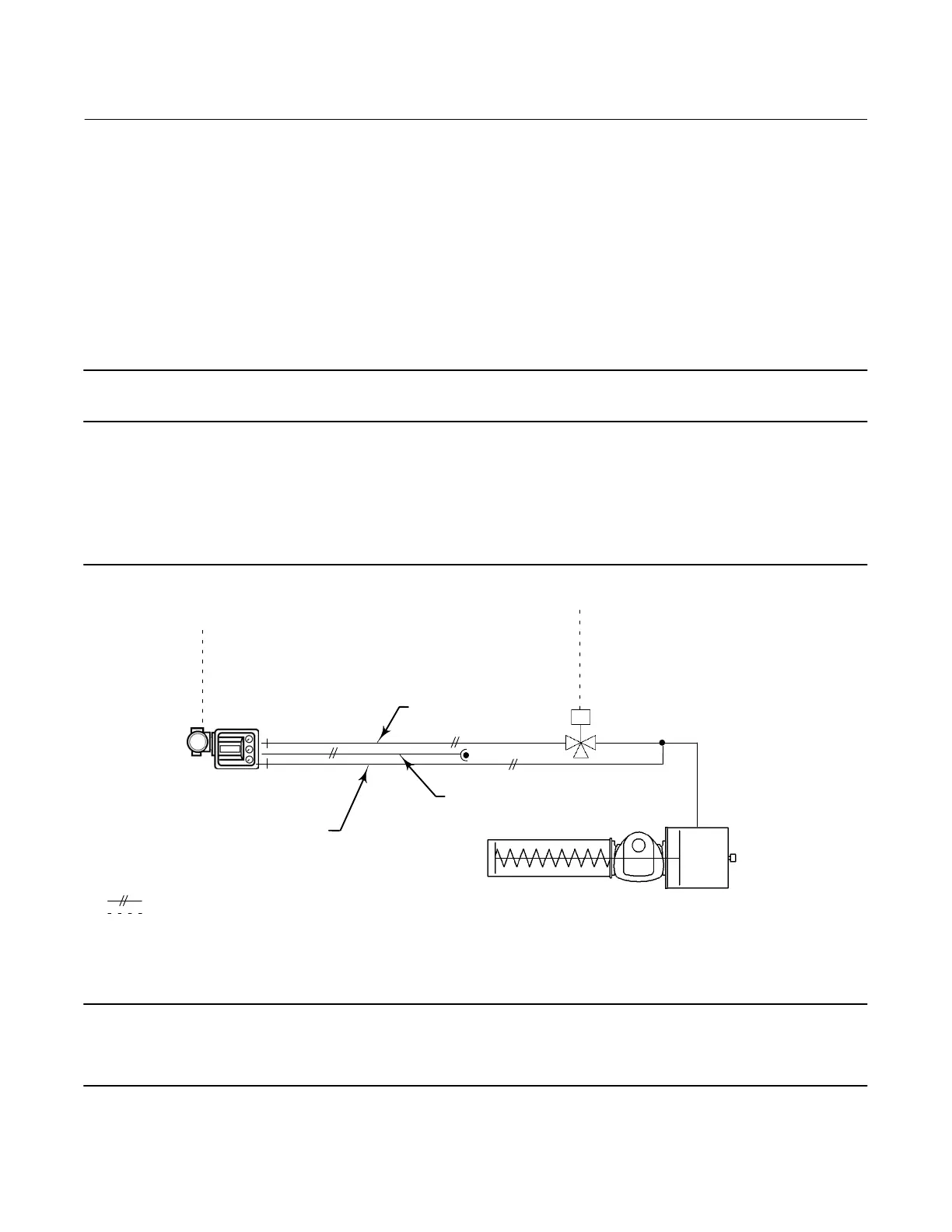
Figure 2‐23. Pneumatic Hookup for Solenoid Testing (Instrument Level ODV only)
24/48 VDC
110/220 VAC, etc.
Port A
CONTROL SIGNAL
(4‐20 mA, 0‐20 mA,
0‐24 VDC)
Port B
SUPPLY PRESSURE
MONITORING LINE
CONTROL LINE
DVC6200 DIGITAL VALVE
CONTROLLER WITH RELAY C
SPRING RETURN ACTUATOR
NOTES:
1/4‐18 NPT X 3/8 OD TUBING
ELECTRICAL WIRING
Note
This application is called “special application” in the Setup Wizard relay selection.
This configuration is not possible with a double‐acting actuator or when using relay A in single‐acting mode.

 Loading...


