Instruction Manual
D103409X012
Installation
May 2013
28
D Ensure that the cover is correctly installed before putting this unit back into service. Failure to do so could result in
personal injury or property damage from fire or explosion.
The DVC6200 can be used with air or natural gas as the supply medium. If using natural gas as the pneumatic supply
medium, natural gas will be used in the pneumatic output connections of the DVC6200 to any connected equipment.
In normal operation the unit will vent the supply medium into the surrounding atmosphere unless it is remotely
vented.
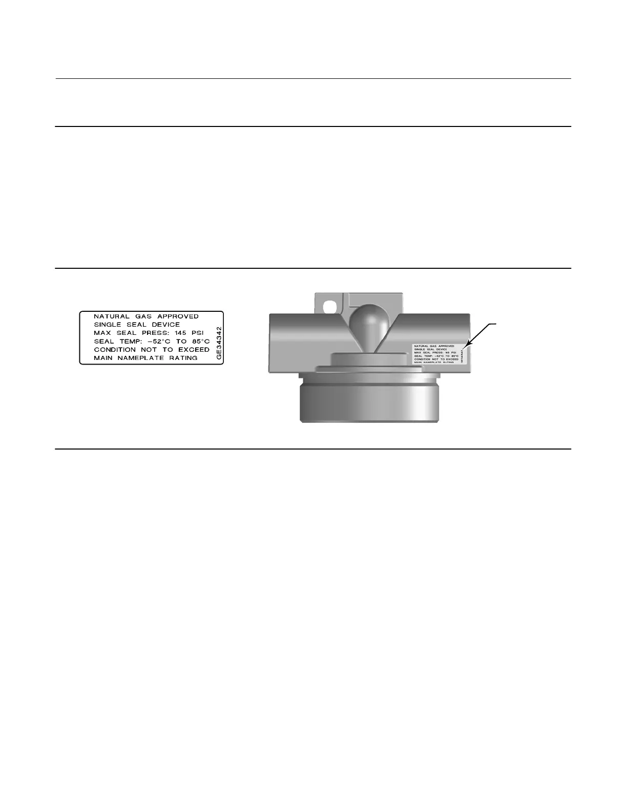
Natural Gas Certified, Single Seal instruments can be identified by the natural gas approval label shown in figure 2‐22.
The Natural Gas Certified, Single Seal device option simplifies conduit sealing requirements. Read and follow all local,
regional, and federal wiring requirements for natural gas installations. Contact your Emerson Process Management
sales office for information on obtaining a Natural Gas Certified, Single Seal DVC6200 digital valve controller.
Figure 2‐22. Gas Certified Label
LABEL LOCATED
ON TOP OF
TERMINAL BOX
Supply pressure must be clean, dry air that meets the requirements of ISA Standard 7.0.01.
Alternatively, natural gas must be clean, dry, oil‐free, and noncorrosive. H
2
S content should not exceed 20 ppm.
A maximum 40 micrometer particle size in the air system is acceptable. Further filtration down to 5 micrometer
particle size is recommended. Lubricant content is not to exceed 1 ppm weight (w/w) or volume (v/v) basis.
Condensation in the air supply should be minimized.
If you are using a 67CFR filter regulator with standard 5 micrometer filter, connect the supply line to the 1/4 NPT IN
connection and attach tubing from the output connection on the filter regulator to the SUPPLY connection on the
instrument. If you are using an integral mounted 67CFR filter regulator, connect the supply to the IN connection on
the regulator.
Output Connection
A factory mounted digital valve controller has its output piped to the supply connection on the actuator. If mounting
the digital valve controller in the field, connect the 1/4 NPT digital valve controller output connection to the
pneumatic actuator input connection.
Single‐Acting Actuators
When using a single‐acting direct digital valve controller (relay A or C) on a single‐acting actuator, connect OUTPUT A
to the actuator pneumatic input. When using a single‐acting reverse digital valve controller (relay B) on a single‐acting
actuator, connect OUTPUT B to the actuator diaphragm casing.
 Loading...


