Instruction Manual
D103409X012
Maintenance and Troubleshooting
May 2013
108
To check the Voltage Available at the instrument, perform the following:
1. Connect the equipment in figure 2‐29 to the field wiring in place of the FIELDVUE instrument.
2. Set the control system to provide maximum output current.
3. Set the resistance of the 1 kilohm potentiometer shown in figure 2‐29 to zero.
4. Record the current shown on the milliammeter.
5. Adjust the resistance of the 1 kilohm potentiometer until the voltage read on the voltmeter is 11.0 volts.
6. Record the current shown on the milliammeter.
7. If the current recorded in step 6 is the same as that recorded in step 4 (± 0.08 mA), the voltage available is
adequate.
8. If the voltage available is inadequate, refer to Wiring Practices in the Installation section.
Checking the Loop Current Without Disturbing the Loop Wiring
WARNING
Personal injury or property damage caused by fire or explosion may occur if this test is attempted in an area which contains
a potentially explosive atmosphere or has been classified as hazardous.
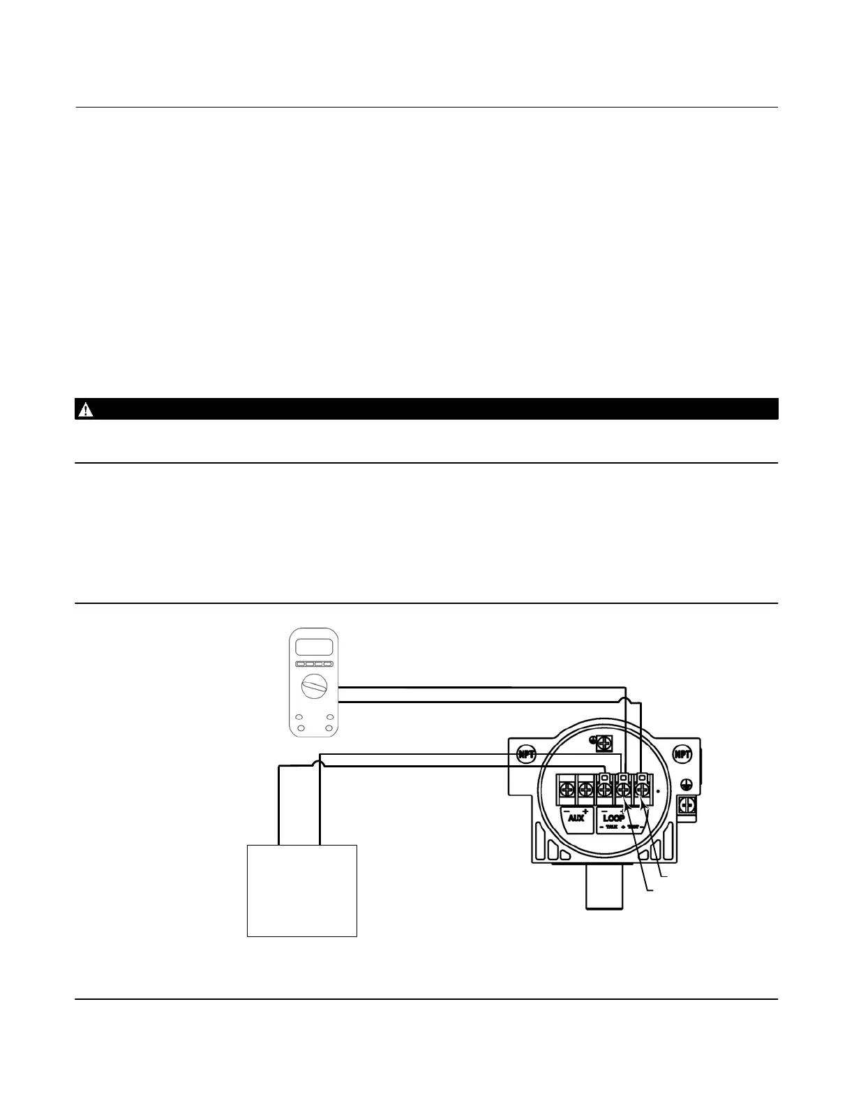
To check the loop current without disturbing the loop wiring perform the following procedure.
1. With the FIELDVUE instrument connected to a current source connect a digital multimeter reading Volts DC ( 0 to 1
VDC or mV scale) to the TEST terminals as shown in figure 7‐8.
2. The reading at the test terminals is proportional to the loop current [0.004 V = 0.004 A (4 MA)] mA of loop current).
Refer to Specifications, table 1‐2, to determine if the current is sufficient.
Figure 7‐8. Check the Loop Current using the TEST Terminals
LOOP + / TEST +
TEST -
DCS SYSTEM
(OR OTHER CURRENT
SOURCE)
4-20mA
CURRENT SOURCE
+
−
LOOP -
LOOP + / TEST +
LOOP + / TEST +
TEST -
NOTES:
1. MULTIMETER MEASURING 0.000 TO 1.0000 VDC
2. TYPICAL READINGS 0.004 VDC TO 0.020 VDC
3. OHM'S LAW—V = I x R, WHERE R = PRECISION 1 OHM RESISTOR, V = I x 1, SO V= I
MULTIMETER
(SEE NOTES
BELOW)
0.020
DVC6200 DIGITAL VALVE
CONTROLLER TERMINAL BOX
 Loading...


