Instruction Manual
D103409X012
Maintenance and Troubleshooting
May 2013
109
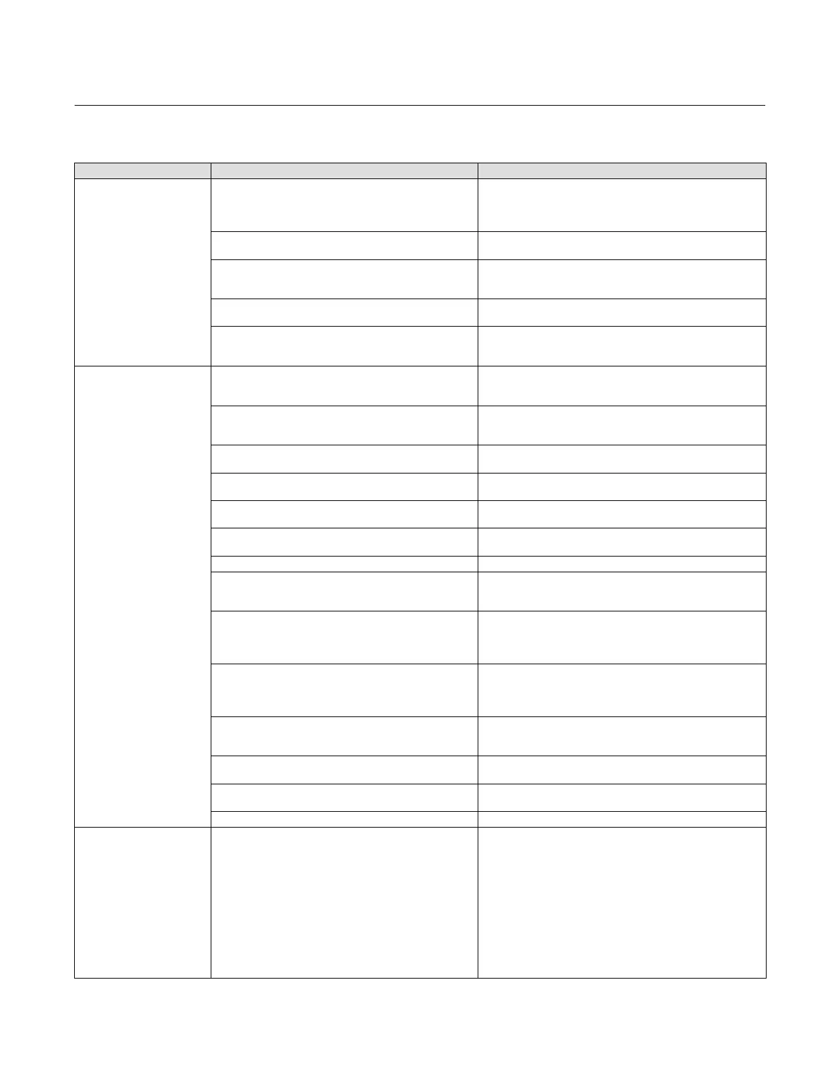
Table 7‐3. Instrument Troubleshooting
Symptom Possible Cause Action
1. Analog input reading at
instrument does not match
actual current provided.
1a. Control mode not Analog. 1a. Check the control mode using the Field Communicator. If in
the Digital or Test mode, the instrument receives its set point as
a digital signal. Control is not based on input current. Change
Control Mode to Analog.
1b. Low control system compliance voltage. 1b. Check system compliance voltage (see Wiring Practices in
the Installation section.
1c. Instrument shutdown due to self test failure. 1c. Check instrument status using the Field Communicator (see
Viewing Instrument Status in the Viewing Device Information
section).
1d. Analog input sensor not calibrated. 1d. Calibrate the analog input sensor (see Analog Input
Calibration in the Calibration section).
1e. Current leakage. 1e. Excessive moisture in the terminal box can cause current
leakage. Typically the current will vary randomly if this is the
case. Allow the inside of the terminal box to dry, then retest.
2. Instrument will not
communicate.
2a. Insufficient Voltage Available. 2a. Calculate Voltage Available (see Wiring Practices in the
Installation section). Voltage Available should be greater than or
equal to 11 VDC.
2b. Controller output Impedance too low. 2b. Install a HART filter after reviewing Control System
Compliance Voltage requirements (see Wiring Practices in the
Installation section).
2c. Cable capacitance too high. 2c. Review maximum cable capacitance limits (see Wiring
Practices in the Installation section).
2d. HART filter improperly adjusted. 2d. Check filter adjustment (see the appropriate HART filter
instruction manual).
2e. Improper field wiring. 2e. Check polarity of wiring and integrity of connections. Make
sure cable shield is grounded only at the control system.
2f. Controller output providing less than 4 mA to loop. 2f. Check control system minimum output setting, which should
not be less than 3.8 mA.
2g. Disconnected loop wiring cable at PWB. 2g. Verify connectors are plugged in correctly.
2h. PWB DIP switch not set properly. 2h. Check for incorrect setting or broken DIP switch on the back
of the PWB. Reset switch or replace PWB, if switch is broken. See
table 7‐2 for switch setting information
2j. PWB failure. 2j. Use a 4-20 mA current source to apply power to the
instrument. Terminal voltage across the LOOP+ and LOOP-
terminals should be 9 to 10.5 VDC. If the terminal voltage is not
9 to 10.5 VDC, replace the PWB.
2k. Polling address incorrect. 2k. Use the Field Communicator to set the polling address (refer
to the Detailed Setup section). From the Utility menu, select
Configure Communicator > Polling > Always Poll. Set the
instrument polling address to 0.
2l. Defective terminal box. 2l. Check continuity from each screw terminal to the
corresponding PWB connector pin. If necessary, replace the
terminal box assembly.
2m. Defective Field Communicator or ValveLink
modem cable.
2m. If necessary, repair or replace cable.
2n. ValveLink modem defective or not compatible
with PC.
2n. Replace ValveLink modem.
2p. ValveLink hardlock defective or not programmed. 2p. Replace if defective or return to factory for programming.
3. Instrument will not
calibrate, has sluggish
performance or oscillates.
3a. Configuration errors. 3h. Verify configuration:
If necessary, set protection to None.
If Out of Service, place In Service.
Check:
Travel Sensor Motion
Tuning set
Zero control signal
Feedback Connection
Control mode (should be Analog)
Restart control mode (should be Analog)
 Loading...


