Instruction Manual
D103409X012
Maintenance and Troubleshooting
May 2013
104
2. Properly orient the PWB assembly (key 50) as you install it into the module base. The two electrical leads from the
I/P converter (key 41) must guide into their receptacles in the PWB assembly and the pressure sensor bosses on the
module base must fit into their receptacles in the PWB assembly.
3. Push the PWB assembly (key 50) into its cavity in the module base.
4. Install and tighten three screws (key 33) to a torque of 1 NSm (10.1 lbfSin).
5. Set the DIP switch on the PWB assembly according to table 7‐2.
Table 7‐2. DIP Switch Configuration
(1)
Operational Mode Switch Position
Multidrop Loop
UP
Point‐to‐Point Loop
DOWN
1. Refer to figure 7‐5 for switch location.
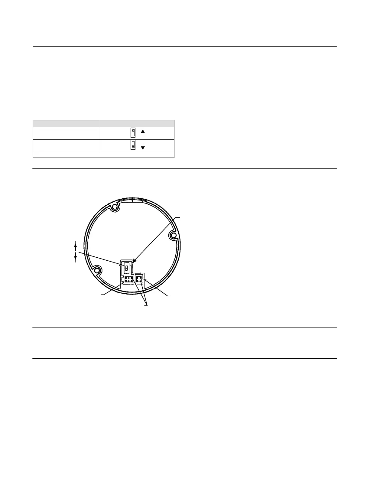
Figure 7‐5. DIP Switch Location
BACK OF PWB ASSEMBLY SUB‐MODULE
DIP SWITCH
UP
DOWN
PINS REMOVED FOR CONNECTOR KEYING
TRAVEL SENSOR
CONNECTOR
TERMINAL BOX CONNECTOR
Note
For the digital valve controller to operate with a 4 to 20 mA control signal, be sure the DIP switch is in the point‐to‐point loop
position, i.e., switch in down position.
6. Reassemble the module base to the housing by performing the Replacing the Module Base procedure.
7. Setup and calibrate the digital valve controller.
 Loading...


