Instruction Manual
D103409X012
Installation
May 2013
36
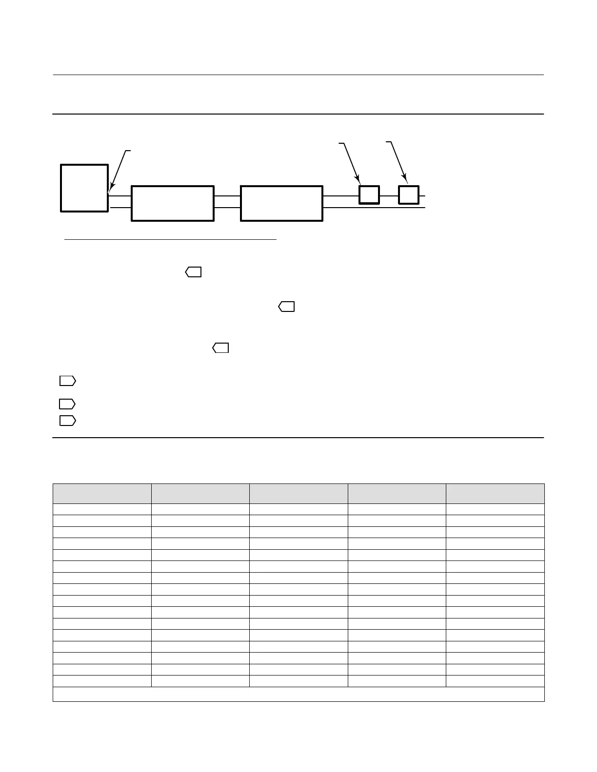
Figure 2‐28. Determining Voltage Available at the Instrument
The voltage available at the instrument is not the voltage measured at the instrument terminals. Once the instrument is
connected, the instrument limits the measured voltage to approximately 9.0 to 10.5 volts.
Obtain filter voltage drop. The measured drop will be different than this value. The measured filter voltage drop
depends upon control system output voltage, the intrinsic safety barrier (if used), and the instrument. See note 3.
HART FILTER
(if used)
CONTROL
SYSTEM
+
-
COMPLIANCE VOLTAGE
VOLTAGE
AVAILABLE AT THE
INSTRUMENT
+
-
R
INTRINSIC SAFETY
BARRIER
(if used)
Control system compliance voltage
= Voltage available at the instrument
– Filter voltage drop (if used)
Example Calculation
18.5 volts (at 21.05 mA)
– 2.3 volts (for HF300 filter)
– Intrinsic safety barrier resistance (if used) x maximum loop current – 2.55 volts (121 ohms x 0.02105 amps)
TOTAL LOOP
CABLE RESISTANCE
– Total loop cable resistance x maximum loop current – 1.01 volts (48 ohms x 0.02105 amps for
1000 feet of Belden 9501 cable)
= 15.19 volts, available—if safety barrier (2.55 volts)
is not used
1
3
NOTES:
1
2
Calculate Voltage Available at the Instrument as follows:
THUM ADAPTER
(IF USED)
– Smart Wireless THUM adapter voltage drop (if used)
2
The voltage drop of the THUM adapter is linear from 2.25 volts at 3.5 mA to 1.2 volts at 25 mA.
3
Table 2‐2. Cable Characteristics
Cable Type
Capacitance
(1)
pF/Ft
Capacitance
(1)
pF/m
Resistance
(2)
Ohms/ft
Resistance
(2)
Ohms/m
BS5308/1, 0.5 sq mm 61.0 200 0.022 0.074
BS5308/1, 1.0 sq mm 61.0 200 0.012 0.037
BS5308/1, 1.5 sq mm 61.0 200 0.008 0.025
BS5308/2, 0.5 sq mm 121.9 400 0.022 0.074
BS5308/2, 0.75 sq mm 121.9 400 0.016 0.053
BS5308/2, 1.5 sq mm 121.9 400 0.008 0.025
BELDEN 8303, 22 awg 63.0 206.7 0.030 0.098
BELDEN 8441, 22 awg 83.2 273 0.030 0.098
BELDEN 8767, 22 awg 76.8 252 0.030 0.098
BELDEN 8777, 22 awg 54.9 180 0.030 0.098
BELDEN 9501, 24 awg 50.0 164 0.048 0.157
BELDEN 9680, 24 awg 27.5 90.2 0.048 0.157
BELDEN 9729, 24 awg 22.1 72.5 0.048 0.157
BELDEN 9773, 18 awg 54.9 180 0.012 0.042
BELDEN 9829, 24 awg 27.1 88.9 0.048 0.157
BELDEN 9873, 20 awg 54.9 180 0.020 0.069
1. The capacitance values represent capacitance from one conductor to all other conductors and shield. This is the appropriate value to use in the cable length calculations.
2. The resistance values include both wires of the twisted pair.

 Loading...


