PARTS DIAGRAMS AND LISTS
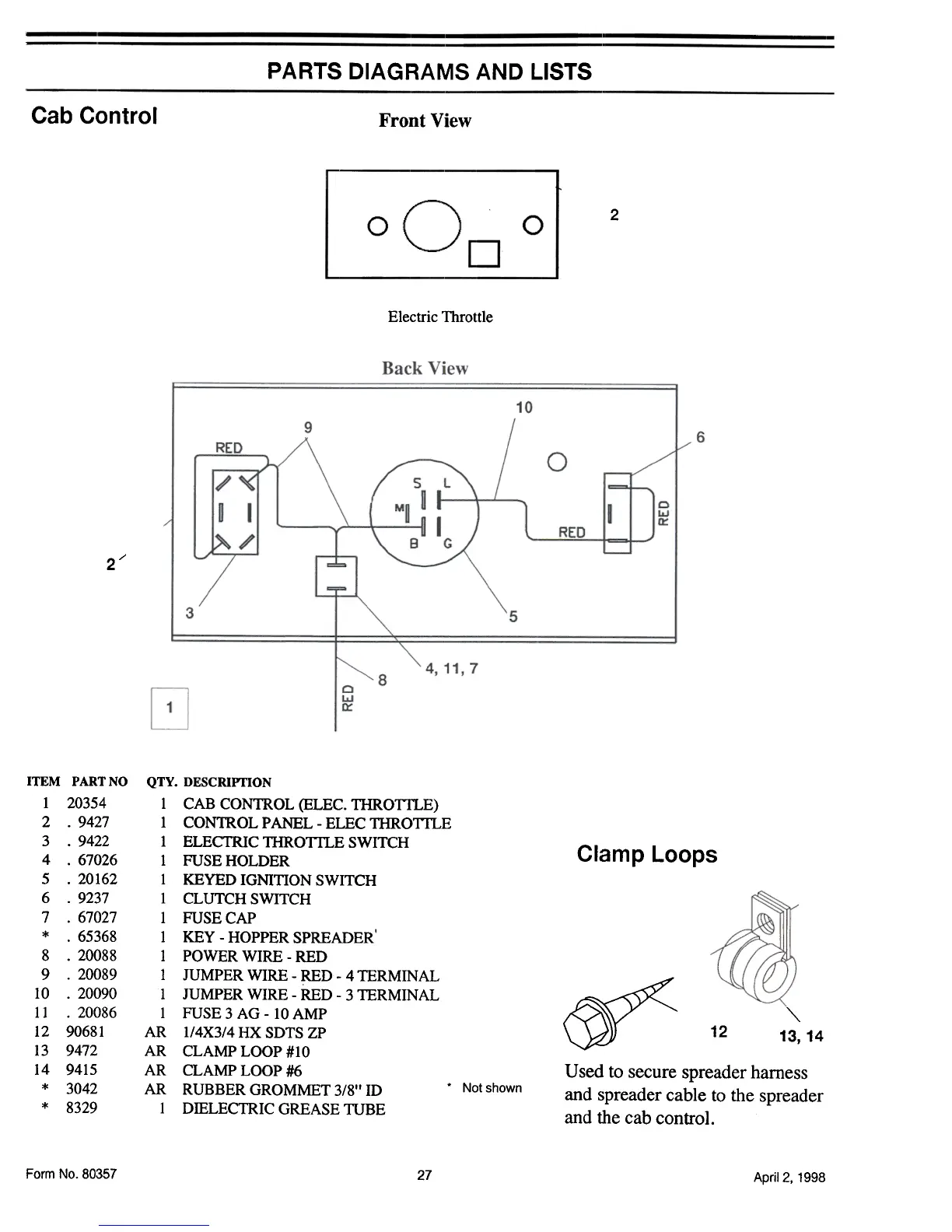
Cab Control
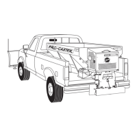
Front View
2
0
0
D
Electric Throttle
2/
ITEM PARTNO
1 20354
2 .9427
3 .9422
4 .67026
5 .20162
6 .9237
7 .67027
* .65368
8 .20088
9 .20089
10 .20090
11 .20086
12 90681
13 9472
14 9415
* 3042
* 8329
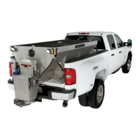
Clamp Loops
QTY. DESCRIPrION
1 CAB CONTROL (ELEC. THROTl1..E)
1 CONTROL PANEL -ELEC THROTl1..E
1 ELEcrRIC THROTl1..E SWITCH
1 FUSE HOLDER
1 KEYED IGNITION SWITCH
1 CLUTCH SWITCH
1 FUSE CAP
1 KEY -HOPPER SPREADER ,
1 POWER WIRE -RED
1 JUMPER WIRE -RED- 4 TERMINAL
1 JUMPER WIRE -RED -3 TERMINAL
1 FUSE 3 AG -10 AMP
AR l/4X3/4HXSDTSZP
AR CLAMP LOOP #10
AR CLAMP LOOP #6
AR RUBBER GROMMET 3/8" ID. Not shown
1 DIELECTRIC GREASE TUBE
~
""'
13, 14
12
Used to secure spreader harness
and spreader cable to the spreader
and the cab control.
Form No.80357
27
April 2, 1998