PARTS DIAGRAMS AND LISTS
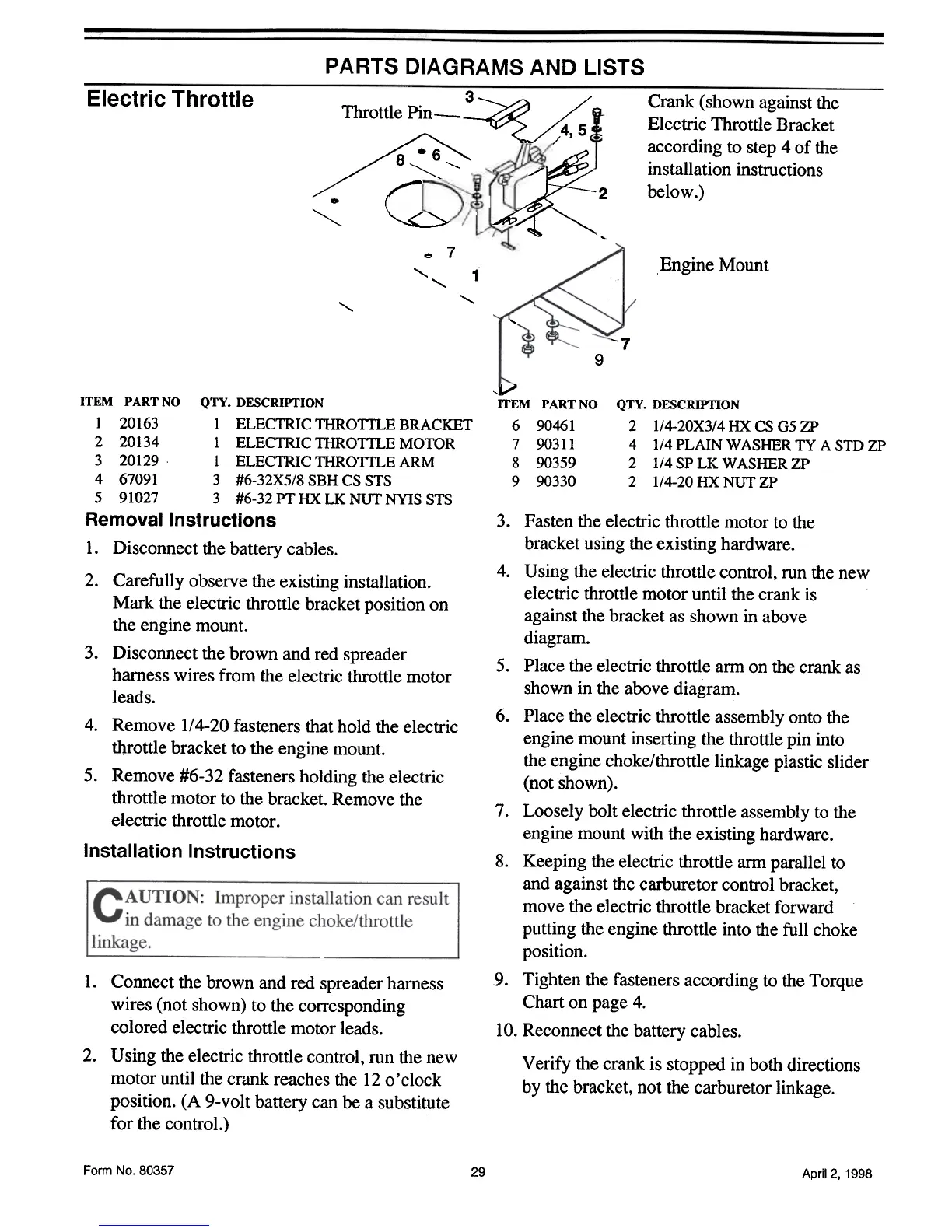
Electric Throttle
Crank (shown against the
Electric Throttle Bracket
according to step 4 of the
installation instructions
below.)
Throttle Pin-
~
/8~,
r
~
3
~
~2
...
,
~
"""
e 7
Engine Mount
"
1
,
,
"
"
-7
9
v
ITEM PARTNO
690461
7 90311
8 90359
9 90330
QTY. DESCRIPTION
2 l/4-20X3/4 HX CS G5 ZP
4 1/4 PLAIN WASHER TY A STD ZP
2 1/4 SP LK WASHER ZP
2 1/4-20 HX NUT ZP
ITEM PARTNO QTY. DESCRIPTION
I 20163 I ELECTRICTHROTfLEBRACKET
2 20134 I ELECTRIC THROTfLE MOTOR
3 20129 I ELECTRIC THROTfLE ARM
4 67091 3 #6-32X5/8 SBH CS STS
5 91027 3 #6-32PTHXLKNUTNYISSTS
Removal Instructions
1. Disconnect the battery cables.
2. Carefully observe the existing installation.
Mark the electric throttle bracket position on
the engine mount.
3. Disconnect the brown and red spreader
harness wires from the electric throttle motor
leads.
4. Remove 1/4-20 fasteners that hold the electric
throttle bracket to the engine mount.
5. Remove #6-32 fasteners holding the electric
throttle motor to the bracket. Remove the
electric throttle motor .
Installation Instructions
3. Fasten the electric throttle motor to the
bracket using the existing hardware.
4. Using the electric throttle control, run the new
electric throttle motor until the crank is
against the bracket as shown in above
diagram.
5. Place the electric throttle arm on the crank as
shown in the above diagram.
6. Place the electric throttle assembly onto the
engine mount inserting the throttle pin into
the engine choke/throttle linkage plastic slider
(not shown).
7. Loosely bolt electric throttle assembly to the
engine mount with the existing hardware.
8. Keeping the electric throttle arm parallel to
and against the carburetor control bracket,
move the electric throttle bracket forward
putting the engine throttle into the full choke
position.
9. Tighten the fasteners according to the Torque
Chart on page 4.
10. Reconnect the battery cables.
1. Connect the brown and red spreader harness
wires (not shown) to the corresponding
colored electric throttle motor leads.
2. Using the electric throttle control, run the new
motor until the crank reaches the 12 o ' clock
position. (A 9-volt battery can be a substitute
for the control.)
Verify the crank is stopped in both directions
by the bracket, not the carburetor linkage.
Form No.80357
29
April 2, 1998