The FJD 3D Excavator Guidance System is a rear-mounted excavator guidance system designed to enhance excavation and construction accuracy through high-precision real-time dynamic positioning technology. It achieves this by reading attitude sensors installed on the excavator and calculating calibrated main pivot sizes to determine the real-time precise 3D position of the bucket. The system displays the current cut-and-fill workload in real time, coordinating with work tasks generated by self-designed transformation software to facilitate digitally guided excavation and construction. This allows the bucket to perform accurately even in blind areas or conditions with poor visibility, significantly improving traditional excavator construction methods.
The system comprises several key components: RTK high-precision positioning equipment, data communication equipment, an on-board tablet computer (serving as the display equipment), attitude transducers, communication antennas, and harnesses. The on-board tablet computer runs an excavator guidance software, independently developed by FJD, which provides real-time statistics on excavation depth, slope, elevation, and satellite positioning of the operating equipment.
Main Hardware and Specifications:
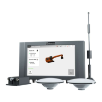
The system's main hardware includes a Control Terminal, Antenna Assembly (GNSS antenna, 4G antenna, and optional Radio antenna), and Attitude Sensors.
Control Terminal:
- Size: 300×190×43mm
- Display: 10.1" capacitive touch LED, backlight 1280*800 pixels, 700cd/m² LCD screen.
- Audio: Double loudspeakers.
- Memory: 2G of run memory, 8G of storage memory.
- Interfaces: Covers a variety of digital and analog output interfaces.
- Power Supply: 10V~30V.
- Signal Coverage: Radio, positioning satellites, 4G, and other signals.
- Operating Temperature: -30°C~+70℃.
- Storage Temperature: -40°C~+85°C.
- IP Rating: IP65.
- Relative Humidity: 0%~95%, at 40 °C (non-condensation).
- Wi-Fi Specification: 2.4GHz frequency band, 2.4GHz~2.5GHz frequency range, 14dB±1.5dB output power.
GNSS Antenna:
- Frequency Range: GPS L1/L2, GLONASS L1/L2, BDS B1/B2/B3.
- Operating Voltage: 3.3V~12V.
- Operating Current: ≤45mA.
- Size: 152*63mm.
4G Antenna (Sucker antenna):
- Frequency Range: B1/B2/B3/B5/B8/B38/B39/B40/B41.
- VSWR: ≤2.0.
- Gain (dBi): 2±0.5.
- Impedance (Ω): 50.
- Polarization: Linear, Vertical.
- Max. Power: 100W.
- Antenna Size: Φ375*82mm.
- Operating Temperature: -20℃~ +65°C.
Radio Antenna (Optional Sucker antenna):
- Frequency Range: 433/470MHz.
- VSWR: ≤2.0.
- Gain (dBi): 2±0.5.
- Impedance (Ω): 50.
- Polarization: Linear, Vertical.
- Max. Power: 100W.
- Antenna Size: Φ495*82mm.
- Operating Temperature: -20℃~+65°C.
Attitude Sensor:
- Axes (Tilt): Pitch, Roll.
- Range: Pitch ±70°, Roll±180°.
- Resolution: <0.05°.
- Max Angular Rate: ≤400°/s.
- Static Accuracy: 0.15°.
- Dynamic Accuracy: 0.50°.
- Temperature Stability: 0.05°.
- Axes (Acceleration): X,Y,Z.
- Range: ±78m/s/s.
- Resolution: 0.01m/s/s.
- Accuracy: ±0.1m/s/s.
- Output Data Rate (Hz): Selectable to 100 Hz.
- Operating Voltage: 4.9V~32V.
- Power: <400mW.
- Operating Temperature: -40℃~ +85°C.
- Protection Class: IP 67.
Main Performance Parameters:
- Static Accuracy: <±3cm (RMS).
- Assisted Operation Accuracy: <±5cm (RMS).
Usage Features:
The FJD 3D Excavator Guidance System is designed for ease of installation and operation, with clear guidelines for ensuring optimal performance and safety.
Installation Safety:
- Avoid installation in environments prone to electromagnetic interference (e.g., large radar stations, transmitting stations, substations), high temperatures, excessive dust, harmful gases, flammable/explosive materials, unstable voltage, significant vibration, or strong noise, as these conditions can hinder equipment operation.
- Do not install where water accumulation, seepage, dripping, or moisture condensation is likely.
- Always follow the hardware installation manual for proper installation and removal.
Removal Safety:
- Avoid frequent removal of the equipment after installation to prevent damage.
- Turn off all power supplies and disconnect all power lines and cables before removal.
Electrical Safety:
- Adhere to local laws and regulations for electrical operations; only qualified personnel should perform these tasks.
- Inspect the work area for potential hazards like wet ground.
- Familiarize yourself with the emergency power switch location and turn it off first in case of an accident.
- Exercise caution when turning off power.
- Keep the equipment dry; no liquids should enter it.
- Maintain distance from wireless transmitting stations, radar transmitting stations, high-frequency/high-current equipment, microwave ovens, and other high-power wireless devices.
- Direct or indirect contact with high voltage or mains power through wet objects can be fatal.
- Improper electrical operations can lead to accidents (fire, electric shock) and severe harm to personnel and equipment.
Installation Location Requirements:
- Install in an open environment with good ventilation and cooling.
- Ensure the mounting position is firm enough to support the control terminal and accessories.
- The installation location should accommodate the control terminal's size, with space for heat dissipation.
Temperature and Humidity Requirements:
- Maintain standard temperature and humidity in the operating environment for normal operation and extended service life.
- Long-term operation outside recommended temperature/humidity ranges can damage the equipment.
- High relative humidity can cause poor insulation, leakage, and material corrosion.
- Low relative humidity can dry and shrink insulating sheets, potentially generating static electricity harmful to circuits.
- Excessively high temperatures significantly reduce equipment reliability, service life, and accelerate aging.
Cleanliness Requirements:
- The environment should be free of salt, acid, and sulfide in the air, as these can accelerate metal corrosion and part aging. Avoid harmful gases (sulfur dioxide, hydrogen sulfide, nitrogen dioxide, chlorine, etc.).
Power Requirements:
- Input voltage should be within 12±1V or 24±1.5V. Lower input voltage may affect accuracy. The impact on accuracy is reduced after the excavator starts.
Installation Steps:
- Control Terminal: Fixed to the cab's door side using U-bolts and nuts, with a bracket handle for tightening.
- Attitude Sensor: Four sensors are installed on the slewing platform, boom, arm, and bucket link, mounted on plates and fastened with screws/nuts. 3M VHB double-sided tape is used for secure attachment. These sensors compensate for terrain data and monitor extension angles.
- Antenna: RTK antennas are installed on the excavator's backside, with one for positioning (Beidou 1) and another for direction (Beidou 2). The 4G sucker antenna is placed in an unobstructed location with magnetic adsorption.
- Harness: Sensor harnesses are routed along the excavator boom and movable parts, connecting to the smart main harness in the cab. Power harnesses connect to the relay's positive terminal and battery's cathode (24V). Smart main harnesses are concealed in the cab, with the main switch conveniently located.
- SIM Card: A 4G-compatible SIM card (supporting specific frequency bands) with activated data service is inserted into the control terminal's T3 slot. APN and network type settings may need configuration via the built-in Android system.
System Commissioning:
- Excavator Condition Checking: Ensure the excavator is stable and all parts function correctly.
- Site Checking: Confirm no tall trees, buildings, or obstacles affect satellite signals within 150 meters. The site should be a level ground (cement or asphalt) at least 50 meters long and 10 meters wide, preferably a non-public road, with no unrelated persons nearby during commissioning.
- Power-on and Startup: Verify correct power supply connection and voltage. After power-on, check if the control terminal's power indicator is on and if the program starts normally.
- Specification Commissioning: Refer to the Software Instruction Manual for FJD 3D Excavator Guidance System for detailed parameter commissioning.
Maintenance Features:
The manual emphasizes several precautions that contribute to the longevity and proper functioning of the device, which can be considered maintenance-related:
- Environmental Control: Avoiding high temperatures, excessive dust, harmful gases, and moisture helps prevent damage and corrosion.
- Electrical Safety: Proper handling of power connections and avoiding contact with high-voltage cables or hot objects prevents electrical faults.
- Physical Security: Fixing the equipment firmly and avoiding frequent removal reduces the risk of physical damage.
- Cleaning: Removing the power plug before cleaning and not using liquids for cleaning are crucial to prevent electrical hazards and damage to components.
- Enclosure Integrity: Not opening the enclosure protects internal components from environmental factors and unauthorized tampering.
These guidelines ensure the system operates reliably and safely, minimizing the need for frequent repairs and extending its service life.