Hardware Installation Manual for FJD 3D Excavator Guidance System
12
Copyright © FJ Dynamics Technology Co., Ltd. All Rights Reserved.
4.2 Installation of Attitude Sensor
4.2.1 Required Materials
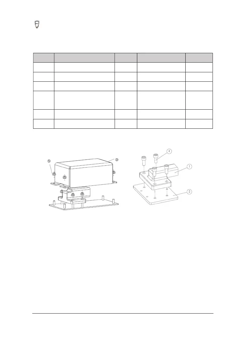
S/N Name Quantity Spec./model Remark
1 Attitude sensor 4
2 Attitude sensor mount 4
3 Protective cover for sensor 2
4
Hexagon socket head cap
screw
8 M5x12
5
Hexagon Nut Class 1 18 M4
6
3M VHB double-sided tape 4
4.2.2 Installation Steps
1. Install the attitude sensor of boom and arm on its mounting plate and fasten it with M5x12 hexagon
socket head cap screws. Install attitude sensors of bucket and car body on the base plate of protective
cover and fasten it by M4 nuts.
2. Stick 3M VHB double-sided tape on the back of the angle sensor.
3. Stick the attitude sensors after selecting the positions of the slewing platform, boom, arm, and
bucket link according to direction as shown in the figure(Note that all are mounted on the left side).
(1) Attitude Sensor (Excavator body)