Manual Flamcomat MK-U G4
We reserve the right to change designs and technical specifications of our products.
14
ENG
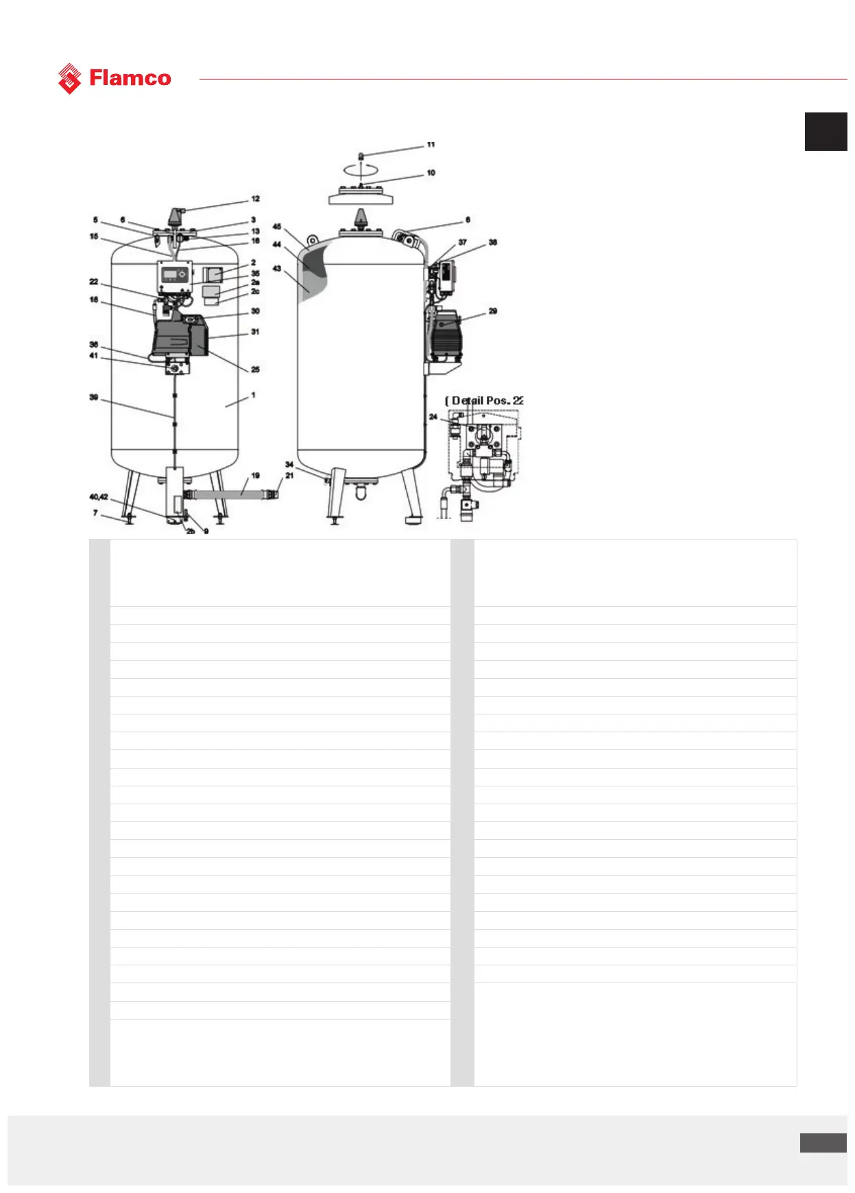
5.5 Component parts, vessels and connection assembly
1 Basic steel vessel with built-in, exchangeable butyl-rubber bladder for
absorption of the expansion water. Exterior corrosion protected, interior
untreated (interior coa-ted***)
23 Connection assembly pressurisation***, safety valve compressed air
compartment compressed air compartment valve 1, pressurisation valve,
non-return valve, pressure connection to compressed air compartment,
pressure connection to compressor
2 Vessel name plate 24 Safety valve to compressed air compartment
2a Control unit name plate 25 Compressor unit K01 - K03, oil-free
2b Advice to remove transport seal 26 Second compressor unit K01 - K03, oil-free
2c Pressurisation warning 27 Compressor unit K04, oil-free
3 Inspection opening 28 Second compressor unit K04, oil-free
4 Inspection opening MK-U 6500-10000 29 Compressor thermal protection, manual reset
5 Li ing hook, load suspension for transport 30 Intake opening compressor
6 Anti-collision protection (compressed air connections) 31 Cooling air inlet compressor
7 Foot-height adjuster 32 Ball valve vessel drain
8 Foot pressure plate MK-U 5000-10000 33 Ball valve system connection
9 Adjusting screw (transport seal volume sensor, removal) 34 Ball valve condensate drain
10 Bleed valve 35 Control unit Flextronic
11 Cover nut (anti-collision protection for bleed valve) 36 Power cable compressor 1, 2** )k*
12 Float vent** 37 Signal wire pressure sensor (SELV)
13 quick-release coupling, connector 38 Pressure sensor
14 Pressure hose, flexible, couplings both sides, length 3000 mm** 39 Signal wire volume sensor (SELV)
15 Pressure hose, flexible, to compressed air comparment of vessel 40 Volume sensor
16 Pressure hose, flexible, to pressure sensor 41 Bladder rupture sensor**
17 Pressure hose, flexible, to safety valve, M-K 400-3500 42 Transport seal pressure sensor
18 Pressure hose, flexible, to compressor 1;2** )k* 43 Water compartment (expansion water)
19 Pressure hose, flexible, to system connection, MK-U 400-10000 44 Bladder
20 System connection M-K, angle 90° 400-3500 l 45 Compressed air compartment
** accessory, optional extra
*** available as special model
)k* second compressor unit
SELV: Safety Extra-Low Voltage design (Safety Extra-Low Voltage)
21 System connection MK-U
22 Connection assembly pressurisation, safety valve compressed air
compartment compressed air compartment valve 1 (1.1***), discharge valve
2; 2.1** )k*, non-return valve 1; 2** )k*, pressure connection to compressed air
compartment, pressure connection to compressor 1; 2 )k*