Manual Flamcomat MK-U G4
We reserve the right to change designs and technical specifications of our products.
19
ENG
6. Assembly
6.1 Setup
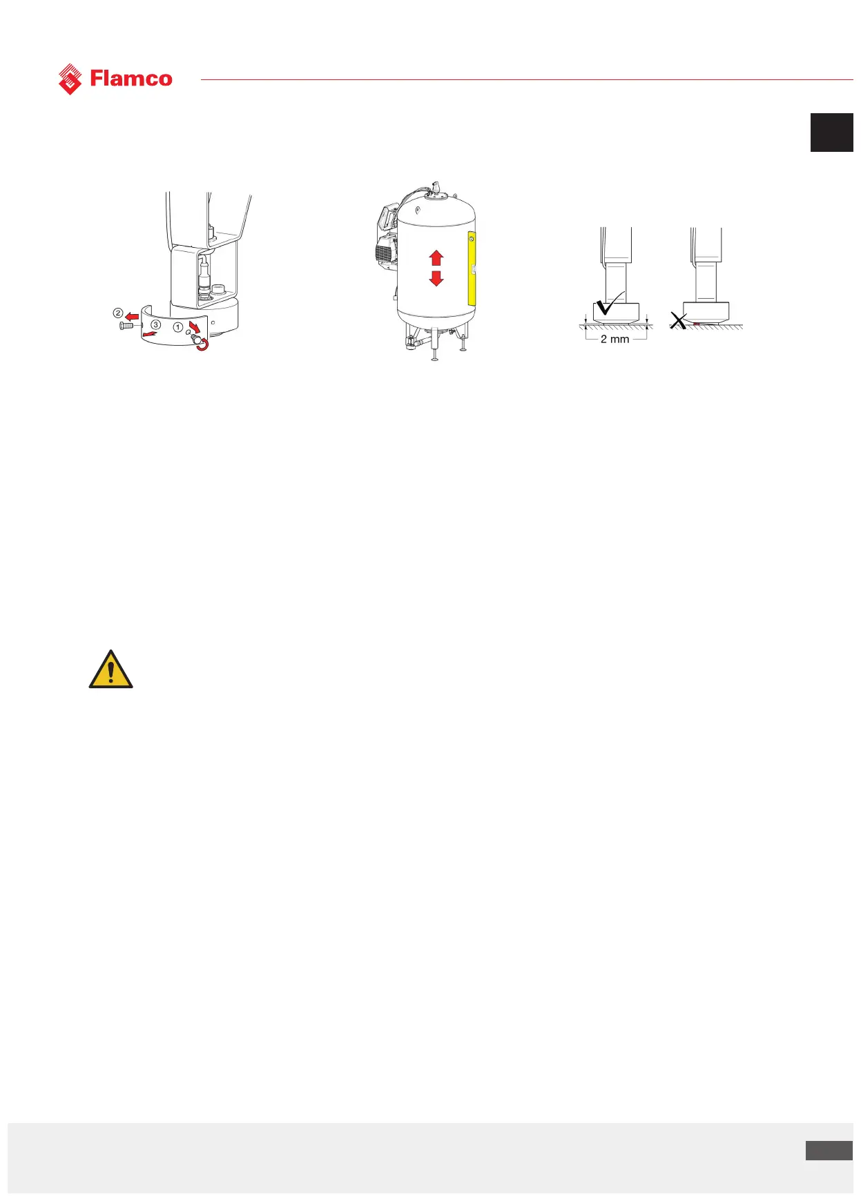
• Remove the transport seal by the capacity sensor once the basic vessel has been erected in the proposed place and no
further positional changes are necessary. Try not to strike this sensor and make sure the sensor is on a surface which does
not impair the function of the sensor pressure-pad.
• Using the foot-height adjuster, adjust the vessel until it is vertical. Use a magnetic spirit level.
• Ensure that no external forces can be exerted on the basic vessel (e.g. tools laid on the vessel, things leaning on the sides).
• Do not fix the basic vessel to the ground on which it is erected (do not use any sort of fastening which can adversely aect
the vessel, e.g. sinking the feet into concrete or lime, welding on the vessel or its feet, clamps and ties on the body of the
structure or appurtenances).
• Place the main vessel and the auxiliary vessel at the same height
6.2 Vessel connection
The system connection should be connected to the heating or cooling system. Appendix 1 shows the installation diagram
and an example installation.
Caution: Close ball valve and shut o system before working on the compressor automat.
Please observe the following specifications before filling and commissioning the pressure-expansion automat:
• The connection should preferably be made in the return flow of the heating or cooling system.
• Please note that a temperature at the system connection > 70 °C would exceed the permissible bladder load and possibly
lead to damage to components.
(Complete insulation of the expansion lines may increase the temperature load on the bladder).
• Ensure that the connection from the main vessel to the system is made only by using the flexible pressure hose that has
been supplied with the vessel.
• Make sure that this connection is made solely with the heat/cool generator, and that there are no external hydraulic
pressure influences present at the point of entrainment (e.g. hydraulic balancers, distributors).
• Use sealant and pipework relevant to the installation; however, please observe at least the maximum permitted
volumetric flow, pressure and temperature values for the expansion line in question.
• Fit isolating equipment in the immediate vicinity of the vessel connection to the system that cannot be closed
unintentionally and preferably includes a fill and drain valve for the water compartments of the vessel. If this equipment is
missing, install this additionally.
• When several vessels are placed in a pressure maintenance system, an extra ball valve is required at the expansion line
before the connection to the main return line. It is recommended to seal this valve to protect against unintentional closing.
• The nominal diameters of the expansion line (supply or return connection from one or more vessels to the main return
line) are to be chosen depending on the installed equipment and the distance to the main return line.
• Pay attention to these recommendations based on practical experience: