FlashCut CNC Section 2 Stepper CNC Controller
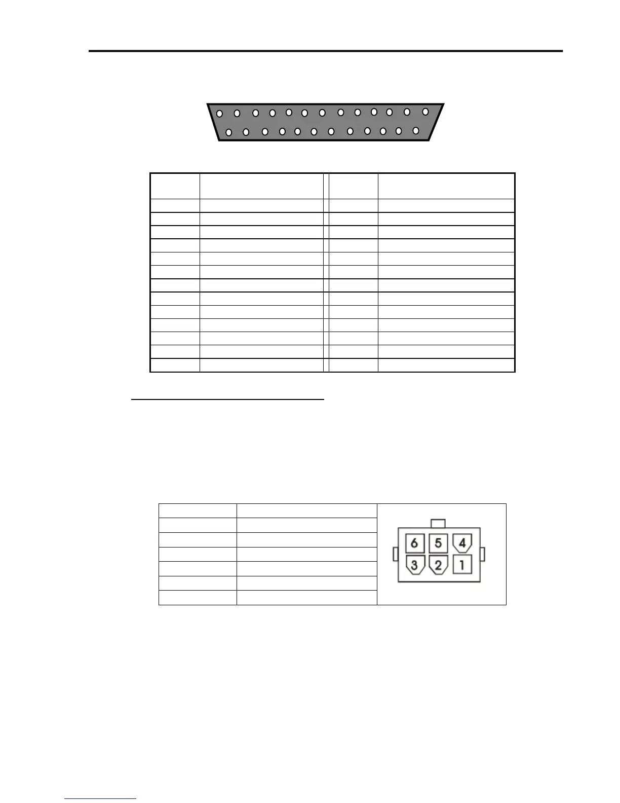
POWER CONNECTOR TO MOTORS – The motors for axes 1-5 plug into these
connectors. The motor lines 1-5 are correlated to any combination of the X, Y, Z, A
and/or B axes in the Motor Signal Setup menu in the FlashCut CNC software. A dummy
plug as installed on any unused motor connector for units with less than 5 axes. Each
motor connector is a Molex Mini Fit Jr. 6 Pin Receptacle with Male Pins (See Section on
Motor Cabling for Mating Connector Information). The pin assignments for the Motor
Connector are as follows (looking from the rear of the unit):