Printed in U.S.A.
Page 28
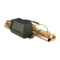
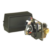
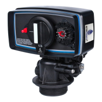
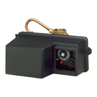
MODEL 9500 ECONOMINDER
Service Assemblies
60037 . . . . . . . . .1600 Brine Valve
10269 . . . . . . . . .Nut, Jam
1 . . . . . 10249 . . . . . . . . .Brine Valve Spring
1 . . . . . 10250 . . . . . . . . .Retaining Ring
3 . . . . . 10329 . . . . . . . . .3/8″ Brass Nut
3 . . . . . 10330 . . . . . . . . .3/8″ Ferrule
3 . . . . . 10332 . . . . . . . . .3/8″ Sleeve
1 . . . . . 16958-02. . . . . . .1600 Brine Valve Stem w/seat
1 . . . . . 12748 . . . . . . . . .Brine Valve Body
1 . . . . . 12550 . . . . . . . . .Quad Ring
1 . . . . . 16960 . . . . . . . . .Tube, Brine Valve
60039 . . . . . . . . .1700 Brine Valve
For Illustration, See Page 17
1 . . . . . 10250 . . . . . . . . .Brine Valve Spring
1 . . . . . 12550 . . . . . . . . .Quad Ring
1 . . . . . 13201 . . . . . . . . .Quad Ring
1 . . . . . 14785 . . . . . . . . .Flow Control Retainer
1 . . . . . 14790 . . . . . . . . .Brine Valve Body
1 . . . . . 14792 . . . . . . . . .Brine Valve End Plug
1 . . . . . 14795 . . . . . . . . .Brine Valve Piston
1 . . . . . 16929 . . . . . . . . .Brine Valve Stem
1 . . . . . 14798 . . . . . . . . .Spacer
2 . . . . . 14811 . . . . . . . . .Piston Seal
1 . . . . . 15310 . . . . . . . . .Brine Valve Spring
1 . . . . . 16123 . . . . . . . . .Nut 1/2″
1 . . . . . 16124 . . . . . . . . .Ferrule 1/2″
1 . . . . . 10269 . . . . . . . . .Nut, Jam
1 . . . . . 15415 . . . . . . . . .Insert
60080 . . . . . . . . .1600 Injector Assembly
For Illustration, See Page 14
1 . . . . . 10227 . . . . . . . . .Injector Screen
1 . . . . . 11893 . . . . . . . . .Injector Cap
1 . . . . . 10229 . . . . . . . . .Injector Cover Gasket
1 . . . . . 10328 . . . . . . . . .90° Elbow 1/4″ NPT x 3/8″ Tube
2 . . . . . 10692 . . . . . . . . .Screw
1 . . . . . 10913 . . . . . . . . .Injector Nozzle
1 . . . . . 10914 . . . . . . . . .Injector Throat
1 . . . . . 11475 . . . . . . . . .Injector Body Gasket
1 . . . . . 17776 . . . . . . . . .Injector Body
60715-16. . . . . . .Tube Assy, 2nd Tank 16″
For Illustration, See Page 14
1 . . . . . 18601 . . . . . . . . .Bag/Screws
4 . . . . . 17052 . . . . . . . . .Coupling
2 . . . . . 17353 . . . . . . . . .90° 1-1/″ 2 Elbow
2 . . . . . 17061 . . . . . . . . .Coupling Retainer
4 . . . . . 17224 . . . . . . . . .O-Ring -224
2 . . . . . 17351-16. . . . . . .16″, 1-1/2″ Copper Tube
8 . . . . . 10231 . . . . . . . . .Screw, Hex
60715-24. . . . . . .Tube Assy, 2nd Tank 24″
1 . . . . . 17351-24. . . . . . .24″ 1-1/2″ Copper Tube
(Replaces 17351-16)
60381. . . . . . . . . 1700 Injector Assembly
For Illustration, See Page 14
1. . . . . . 11893. . . . . . . . . Injector Cap
1. . . . . . 10229. . . . . . . . . Injector Cover Gasket
1. . . . . . 17777. . . . . . . . . Injector Body
1. . . . . . 14801. . . . . . . . . Injector Nozzle
1. . . . . . 14802. . . . . . . . . Injector Throat
1. . . . . . 14803. . . . . . . . . Injector Screen
2. . . . . . 14804. . . . . . . . . Screw
1. . . . . . 14805. . . . . . . . . Injector Body Gasket
60108. . . . . . . . . 9500 Piston Assembly - Upper
For Illustration, See Page 14
1. . . . . . 11335. . . . . . . . . Screw
1. . . . . . 14309. . . . . . . . . Piston Rod Retainer
1. . . . . . 17110. . . . . . . . . Piston
1. . . . . . 17212. . . . . . . . . End Plug Assembly
1. . . . . . 16957. . . . . . . . . Piston Rod
60109. . . . . . . . . 9500 Piston Assembly - Lower
For Illustration, See Page 14
1. . . . . . 11335. . . . . . . . . Screw
1. . . . . . 14309. . . . . . . . . Piston Rod Retainer
1. . . . . . 17111. . . . . . . . . Piston
1. . . . . . 17212. . . . . . . . . End Plug Assembly
1. . . . . . 16956. . . . . . . . . Piston Rod
60134. . . . . . . . . 9500 Seal and Spacer Kit - Upper
For Illustration, See Page 14
5. . . . . . 16101. . . . . . . . . Seal
4. . . . . . 16638-01 . . . . . . Spacer
60133. . . . . . . . . 9500 Seal and Spacer Kit - Lower
For Illustration, See Page 14
11. . . . . 16101. . . . . . . . . Seal
8. . . . . . 16638-01 . . . . . . Spacer
1. . . . . . 17092. . . . . . . . . Spacer
60610-01 . . . . . . 9500 Meter Assembly - Std. Range
For Illustration and Parts List
See Page 19
60610-02 . . . . . . 9500 Meter Assembly - Ext. Range
For Illustration and Parts List,
See Page 19
60420. . . . . . . . . 9500 Powerhead Assembly
See “Parts Price List”
60136-9500 . . . . 9500 Service Repair Kit
See “Parts Price List”
Flow Controls
60366-50 . . . . . . Fleck flow control 5.0 GPM1″ NPT
60366-70 . . . . . . Fleck flow control 7.0 GPM1″ NPT
60708-10 . . . . . . Fleck flow control 10.0 GPM 1″ x 3/4″ NP
60708-12 . . . . . . Fleck flow control 12.0 GPM 1″ x 3/4″ NP
60708-15 . . . . . . Fleck flow control 15.0 GPM 1″ x 3/4″ NP
60708-20 . . . . . . Fleck flow control 20.0 GPM 1″ x 3/4″ NP
60708-25 . . . . . . Fleck flow control 25.0 GPM 1″ x 3/4″ NP