Printed in U.S.A.
Page 4
MODEL 9500 ECONOMINDER
General & Commercial Installation Checklist (Cont’d.)
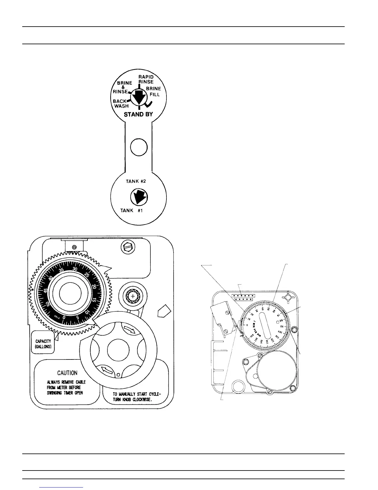
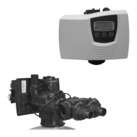
13. Tank #1 has control
valve.
Tank #2 has the
adapter.
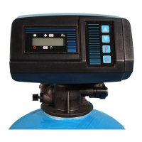
Look on the right side
of the control valve, it
has indicators which
tell you which posi-
tion the control valve
is in during regenera-
tion and which tank is
IN SERVICE. Photo
on the right indicates
the valve is in the ser-
vice position and tank
#1 is supplying condi-
tioned water. Tank #2
is on standby.
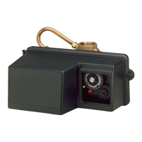
NOTE: Make sure the meter cable is not inserted in the
meter dome. Swing the timer out to expose the program
wheel Figure 2 (to swing timer out) grab onto the lower
right corner of timer face Figure 1 and pull outward.
14. Cycle timer into backwash position. Turn manual knob
(figure 1) so that the micro switch is riding on the 1st
set of pins (figure 2). In this position the tanks will
switch (lower piston) and the control valve will move
to the backwash position (upper piston). You must
wait until the positioning of upper and lower pistons
has stopped before advancing the timer further. If
advanced too fast the control will not home into the
service position (it will not advance to any other
position). To correct this, rotate the manual knob back
to service and start again into backwash. Note: once
valve has positioned itself into the backwash cycle,
the homing circuit is locked in.
With all the air backwashed out, slowly cycle the timer
to the brine position; rapid rinse; and brine tank refill.
You must wait for the control drive motor to position
itself in each cycle and stop, before advancing on to
the next position.
Once back in the service position, cycle the control
valve again into the backwash position. The tanks will
switch again, and you will backwash the air head out
of the other tank. Cycle the control back to the service
position. Leave the timer in the open position.
DO NOT INSERT METER CABLE YET.
NOTE: 2 motors are available, 1/15 RPM will have a 82
min. reg. time available.
BRINE & RINSE
SECTION
(2 MIN. PER HOLE)
PIN STORAGE
PROGRAM
WHEEL FOR
CONTROL OF
REGENERATION
CYCLE
RAPID
RINSE
SECTION
(2 MIN.
PER PIN)
BRINE TANK
REFILL
SECTION
(2 MIN.
PER HOLE)
BACKWASH
SECTION
(2 MIN. PER PIN)
Figure 2