EasyManua.ls Logo

Flintec FT-112 - 4.6 Electrical Connections

Flintec FT-112
170 pages
Print Icon
To Next Page IconTo Next Page
To Previous Page IconTo Previous Page
Loading...
FT-112(D) Panel Weighing Indicator, Technical Manual, Rev.1.0.0, May 2019 Page 18 of 170
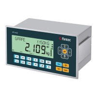
Housing
Front view Side view
Panel cut sizes
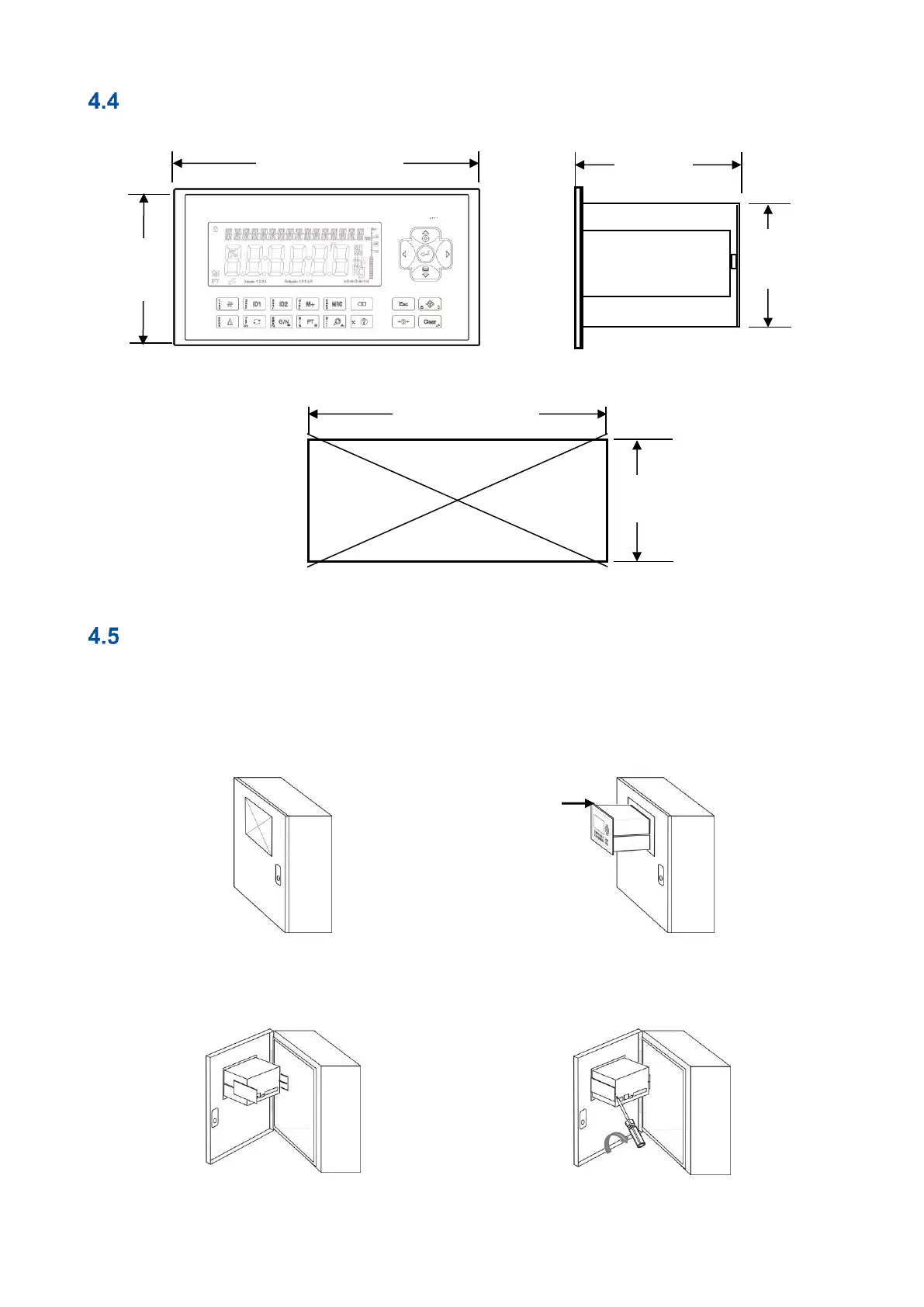
Mechanical Installation
Before starting the installation, prepare the weighing indicator location on the cabinet front.
Prepare the Protective Earth (PE) cable to grounding the FT-112(D) Panel housing. The protective earth
should be as good as possible for scale reliability.
Use high quality and EMC certified DC power source in the cabinet.
Follow the requirements on cabling. Refer to page 16.
Cut the panel of the cabinet to install the
instrument.
Insert the instrument into the panel after placing
the waterproof sealing rubber between the panel
and FT-112(D) Panel.
Place holder parts of the instrument to the both
side of the instrument.
Use 2 pcs M4 screws to mount the instrument to
the panel after alignment.
112,5 mm
(4.43")
91 mm
(3.58")
205mm (8.07") )
108 mm
(4.25")
186 mm (7.32")
92 mm
(3.62")