Do you have a question about the Flintec FT-112 and is the answer not in the manual?
General introduction to the FT-112(D) Panel weighing indicator's features and applications.
Technical specifications for analogue and digital load cells, including A/D converter, resolution, and connections.
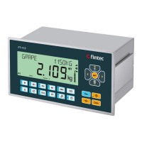
Description of the front panel layout, display symbols, and key functions of the FT-112(D) Panel.
Information on keylock and different password types (User, Service) for accessing instrument functions.
Guidelines for environment, cabling, electrical connections, and peripheral placement during installation.
Instructions for safely cleaning the FT-112(D) Panel weighing indicator, emphasizing care for its environment.
Environmental guidelines for disposing of the FT-112(D) Panel weighing indicator in compliance with WEEE directive.
Details on the physical dimensions and housing of the FT-112(D) Panel weighing indicator.
Step-by-step instructions for mechanically installing the FT-112(D) Panel weighing indicator into a cabinet.
Detailed procedures for connecting analogue and digital load cells, serial ports, and other interfaces.
Covers zeroing, automatic zero corrections, basic weighing, and taring features of the indicator.
Explains advanced features like programmable keys, high resolution, unit change, dynamic weighing, and preset taring.
Details on activating, recording, recalling, and formatting the Alibi memory for weight data recording.
Steps to enter the programming menu, including password entry and accessing main blocks.
How to use fast access keys to quickly reach specific parameter blocks for common operations.
Procedures for exiting the programming menu, including saving or discarding changes.
Explanation of the main programming blocks, sub-blocks, parameters, and navigation within the menu structure.
Instructions for performing scale calibration, including scale definition, test weight usage, and linearity correction.
Step-by-step guide for addressing RC3D digital load cells and manually addressing individual cells.
Procedures for entering, recording, and selecting identification data using ID1 and ID2 keys.
Overview of SmartAPP function, its applications like checkweighing, and operator guidance features.
Guide to classifying products into ranges, starting/stopping the operation, and using SmartAPP features for this application.
How to use checkweighing to verify product tolerance against a target weight, including operation diagrams and I/O functions.
Detailed explanation of the filling application, including product entries, start/stop procedures, SmartAPP usage, and digital I/O.
Information on the peak hold application for detecting broken points in material testing, including product entries and operation.
How to perform horizontal and vertical totalization operations, including displaying and deleting totals.
Functions of digital inputs and outputs during basic weighing operations, mapped to relevant parameters.
How digital I/O functions are set for specific applications like weighing, classifying, filling, and peak hold.
Detailed functions of digital inputs, including key functions, basic peak, hold, and remote input over fieldbus/BSI.
Explanation of digital output functions, including free setpoints, thresholds, windows, and control modes.
Details on continuous data output structure, status bytes, and data format tables.
How fast continuous data output works, its format, and parameters for controlling data transfer speed.
Information on print mode data outputs, including single line, multi-line, and EPL formats.
Steps for designing and printing labels using the EPL format with the instrument's software.
Explanation of the BSI data structure for communication with PCs and PLCs, including general rules and status tables.
Explanation of the analogue output function, its range, and how it relates to gross load and error conditions.
Information on Modbus RTU and TCP/IP interfaces, data formats, and parameter setup for communication.
Configuration and parameters for the Ethernet TCP/IP interface, including IP settings and software options.
Information on the Profibus DP interface, including baud rates, LEDs, and data format.
Information on the Profinet interface, including connection types, LEDs, data format, and GSDML configuration.
Details on the CANopen interface, including baud rates, LEDs, EDS configuration, and data structure.
Data format specifications for weight values in EtherNet/IP communication.
Configuration parameters for the EtherNet/IP interface, including IP address, gateway, and host name.
EDS configuration for PLC programmers using EtherNet/IP interface.
Data structure details for EtherNet/IP communication, referencing Appendix 1.
Data format specifications for weight values in EtherCAT communication.
ESI configuration for PLC programmers using the EtherCAT interface.
Data structure details for EtherCAT communication, referencing Appendix 1.
Data format specifications for weight values in CC-Link communication.
CC-Link configuration details for PLC programmers, including station information.
Data structure details for CC-Link communication, referencing Appendix 1.
Data format specifications for weight values in Powerlink communication.
XDD configuration for PLC programmers using the Powerlink interface.
Data structure details for Powerlink communication, referencing Appendix 1.
Data format specifications for weight values in CC-Link IE Field communication.
CC-Link IE configuration details for PLC programmers, including station information.
Data structure details for CC-Link IE Field communication, referencing Appendix 1.
Data structure for FT-112(D) Panel output to PLC input across different protocols.
Data structure for FT-112(D) Panel output to PLC input specifically for the CANopen protocol.
Information on sealing the calibration switch to maintain approved scale integrity.
Details on sealing the load cell connector for approved scale integrity.
Procedure for sealing the Alibi SD card slot to ensure data integrity for approved scales.
| Protection Class | IP65 |
|---|---|
| Storage Temperature | -20°C to +60°C |
| Weight | 0.7 kg |
| Display | 5.7 inch LCD, 320 x 240 pixels |
| Input Voltage | 12-24 V DC |
| Communication Interface | RS232, RS485, Ethernet |