FT-112(D) Panel Weighing Indicator, Technical Manual, Rev.1.0.0, May 2019 Page 25 of 170
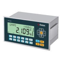
4.6.7 Profibus PB
Figure 4.14 - PLC Connection
PROFIBUS Connector pin configuration (DB9F)
Positive RxD / TxD, RS-485 level
+5V termination power (isolated)
Negative RxD / TxD, RS-485 level
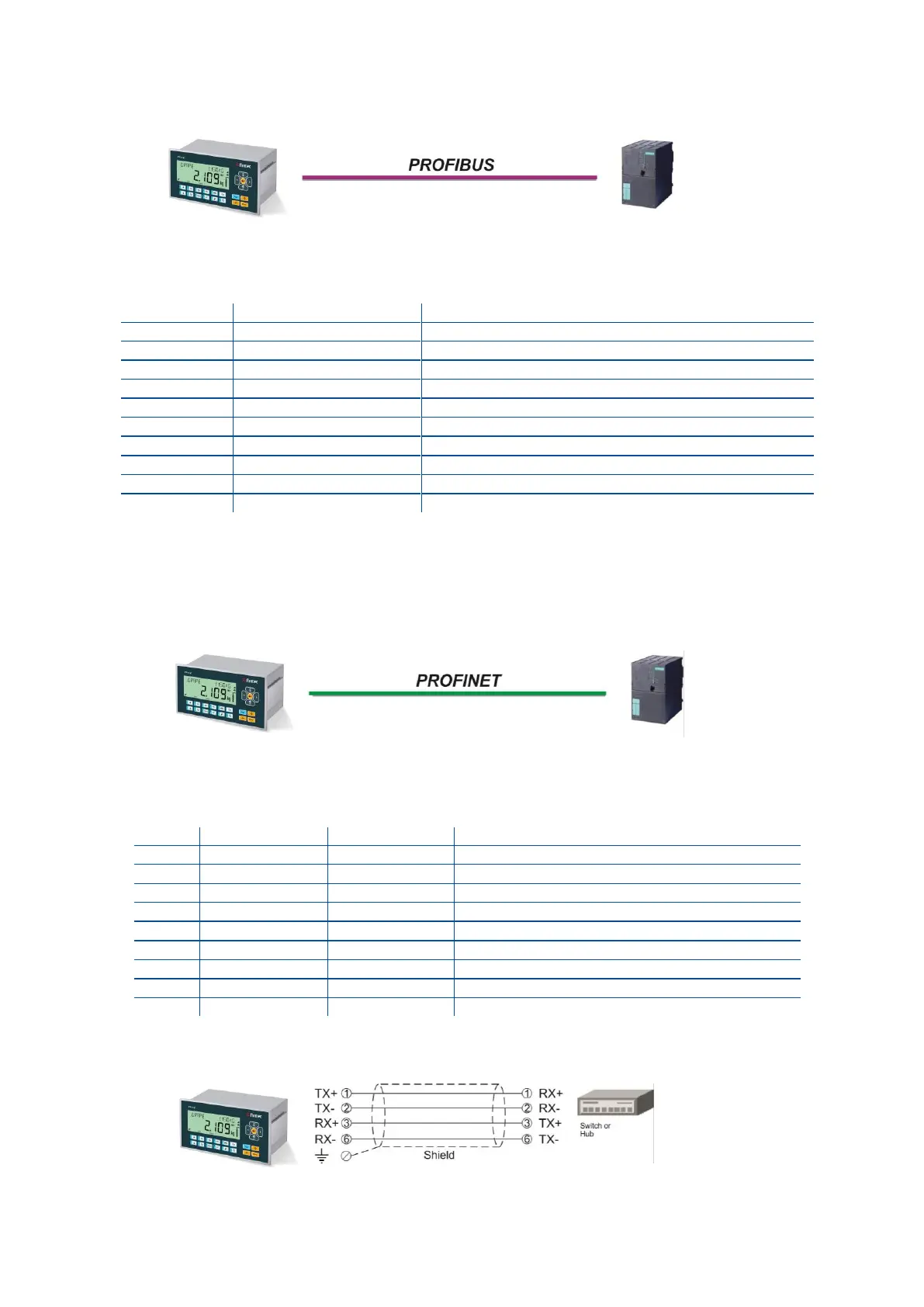
4.6.8 Profinet
Figure 4.15 - PLC Connection
PROFINET Connector pin configuration (RJ45)
Differential Ethernet transmit data +
Differential Ethernet transmit data −
Differential Ethernet receive data +
Differential Ethernet receive data −
The HUB connection cabling will be a direct connection as shown below:
Figure 4.16 - HUB connection