FT-112(D) Panel Weighing Indicator, Technical Manual, Rev.1.0.0, May 2019 Page 24 of 170
4.6.6 Ethernet TCP/IP
The use of the Ethernet port on the main PCB and its data formats are shown in the Table 4.9 and its pin
configuration is shown in Table 4.10. Refer to Section 6 of the manual to configure this interface. Use the RJ45
connecter with metal body and connect shield of the Ethernet cable to the metal body of the connector.
Interfacing with Printer, PC, PLC, remote display etc.
Continuous, Fast Continuous, Printer, BSI Protocol or Modbus TCP
Table 4.9 – Data formats of Ethernet port
Differential Ethernet transmit data +
Differential Ethernet transmit data −
Differential Ethernet receive data +
Differential Ethernet receive data −
Metal body of the RJ45 connector.
Table 4.10 – Pin configuration of RJ45 Ethernet connector
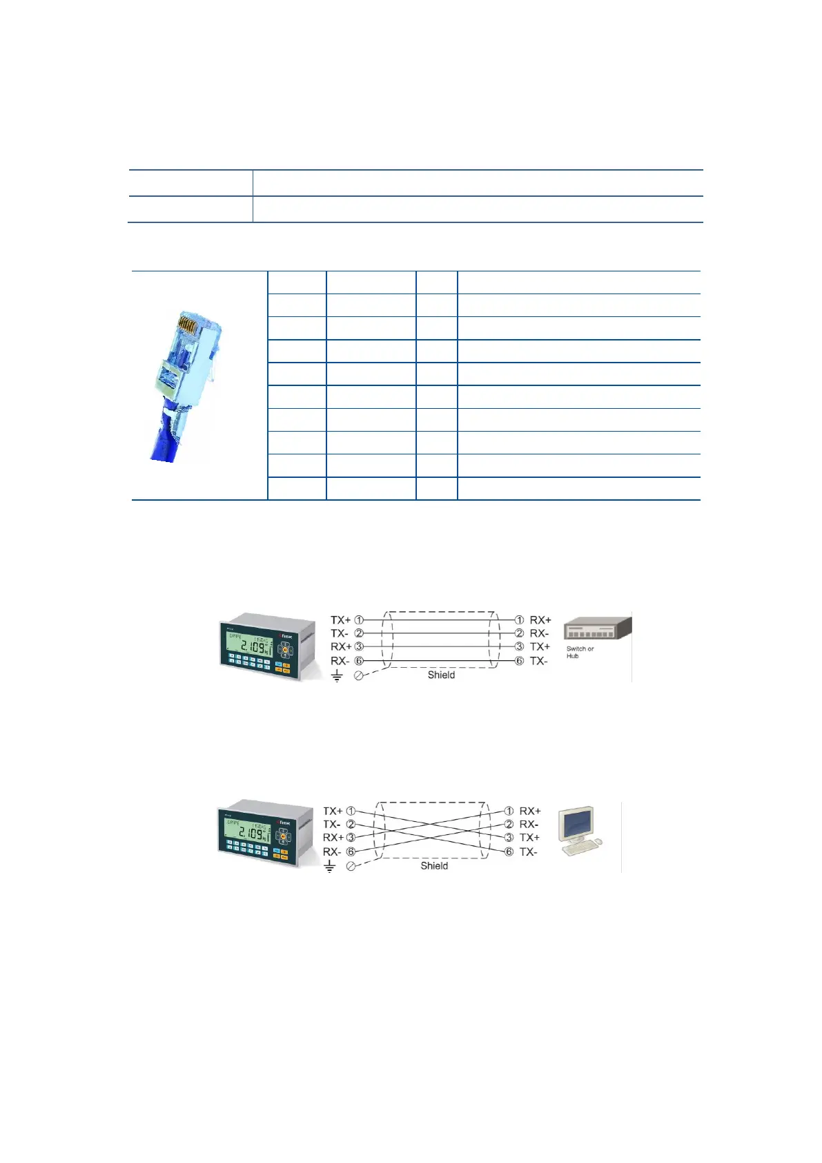
The HUB connection cabling is a direct connection as shown below:
Figure 4.12 - HUB connection
The PC connection cabling is done via cross cable as shown below. IP address blocks and gateway address
of FT-112(D) Panel and PC should be the same in cross connection.
Figure 4.13 - PC connection with cross cable
Important note: Disconnect Indface2x set up PC software before Ethernet interfacing.