EasyManua.ls Logo

Flintec FT-112 - Ethercat; CC-Link

Flintec FT-112
170 pages
Print Icon
To Next Page IconTo Next Page
To Previous Page IconTo Previous Page
Loading...
FT-112(D) Panel Weighing Indicator, Technical Manual, Rev.1.0.0, May 2019 Page 28 of 170
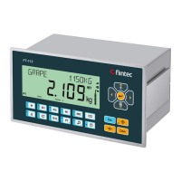
4.6.11 EtherCAT
Figure 4.22 PLC Connection
EtherCAT Connector pin configuration (RJ45)
Pin
Signal
DIR
Description
1
TX+
Out
Differential Ethernet transmit data +
2
TX−
Out
Differential Ethernet transmit data −
3
RX+
In
Differential Ethernet receive data +
6
RX−
In
Differential Ethernet receive data −
4
Not used
Terminated
5
Not used
Terminated
7
Not used
Terminated
8
Not used
Terminated
Shield
Chassis ground
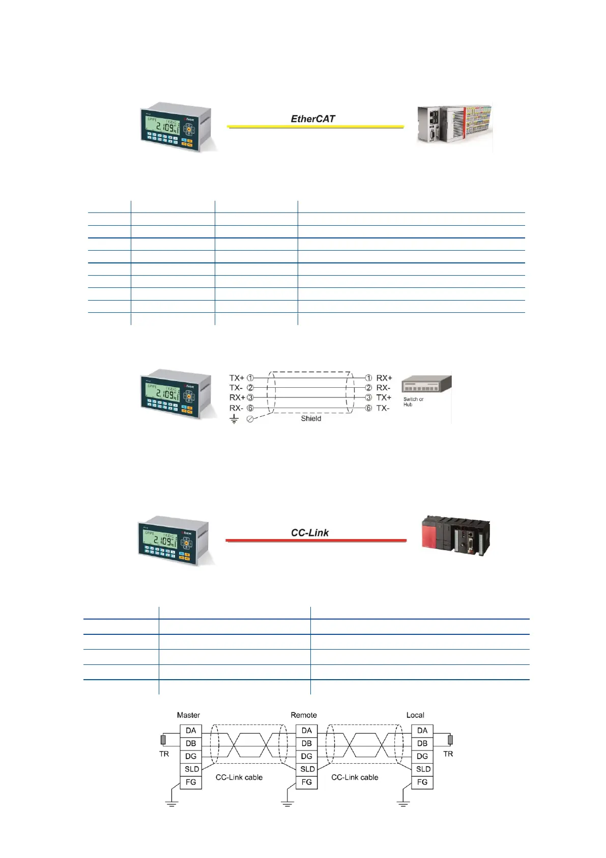
The HUB connection cabling will be a direct connection as shown:
Figure 4.23 - HUB connection
4.6.12 CC-Link
Figure 4.24 - PLC Connection
CC-Link Connector pin configuration
Pin
Signal
Description
1
DA
PositiveRS485 Rxd/TxD
2
DB
NegativeRS485 Rxd/TxD
3
DG
Signal ground
4
SLD
Cable Shield
5
FG
Protective Earth