FT-112(D) Panel Weighing Indicator, Technical Manual, Rev.1.0.0, May 2019 Page 29 of 170
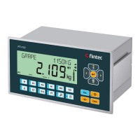
4.6.13 Powerlink
Figure 4.25 - PLC Connection
Powerlink Connector pin configuration (RJ45)
Differential Ethernet transmit data +
Differential Ethernet transmit data −
Differential Ethernet receive data +
Differential Ethernet receive data −
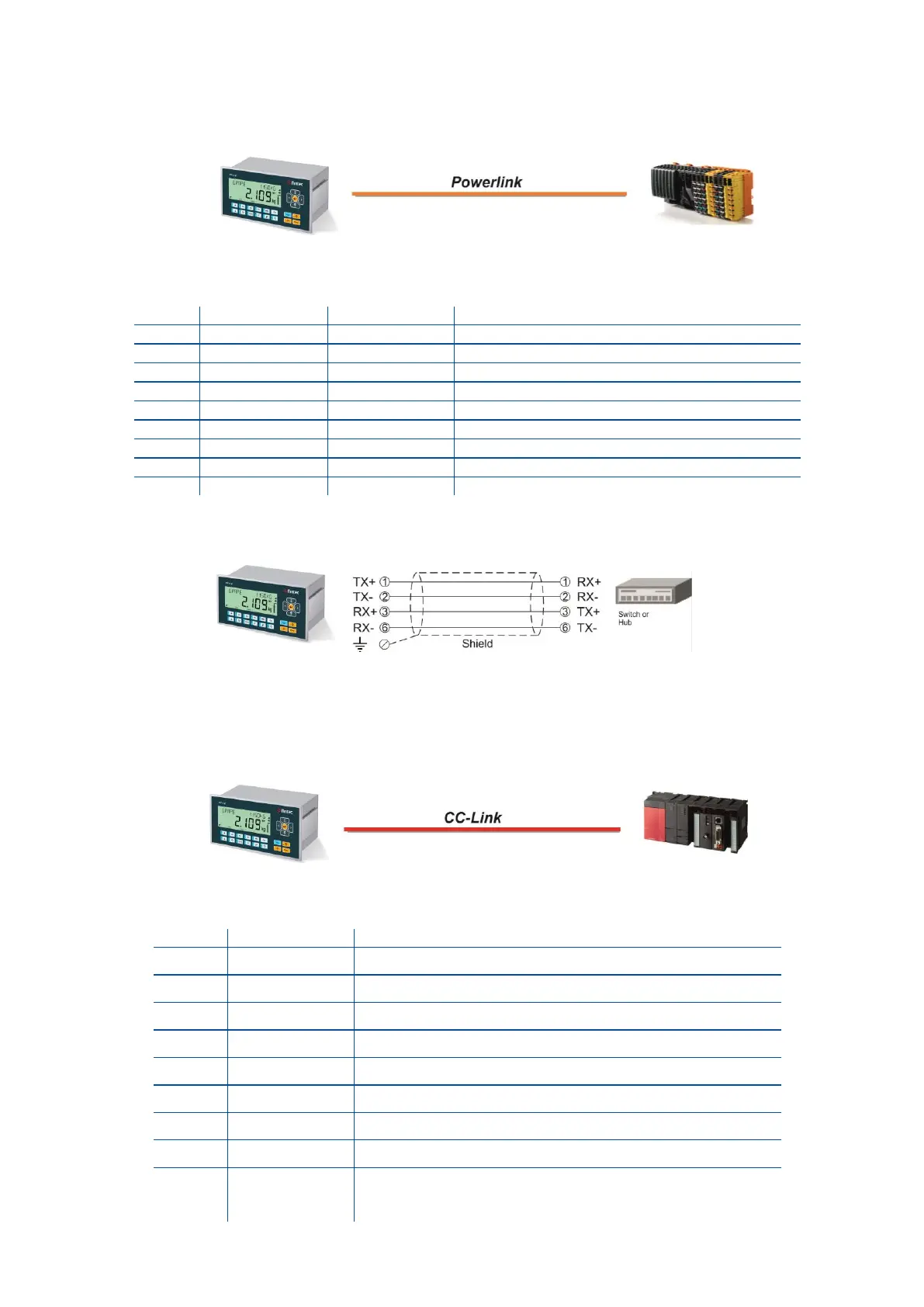
The HUB connection cabling will be a direct connection as shown below:
Figure 4.26 - HUB connection
4.6.14 CC-Link IE
Figure 4.27 - PLC Connection
CC-Link IE Field Connector pin configuration
Transmit/Receive 1 positive
Transmit/Receive 1 negative
Transmit/Receive 2 positive
Transmit/Receive 3 positive
Transmit/Receive 3 negative
Transmit/Receive 2 negative
Transmit/Receive 4 positive
Transmit/Receive 4 negative
Connected to FE through a 1 nF capacitor and a 1
Mohm resistor. Note that the connector shields are
separated to prevent ground currents.