TAU-0035-00-10, version 100 April 2009 5-1
5 Overview of the Electrical Interface
5.1 Input Power
The Tau camera operates from DC power per the specifications given below. It is common in
simple operational scenarios to use an inexpensive wall-powered adapter. This type of adapter is
what is included with the Accessory Kit. The connector pin-out tables indicate where power is to
be applied (PWR_IN and GND pins).
The camera operating in a steady-state condition consumes less than 1W of power. During
start up or when the shutter is operating for the camera’s periodic calibration, peak power
levels of 5W (sustained for less than one second) are typical.
Caution!
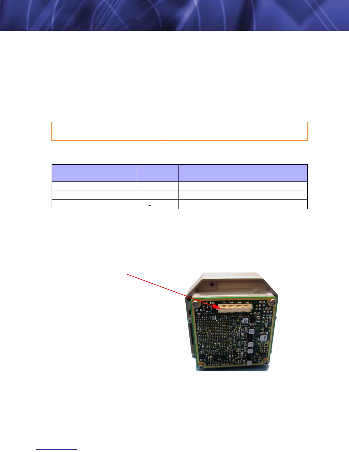
5.2 Hirose 50-Pin Connector
In the Tau camera’s simplest form (no accessories attached), one connector provides the
electrical interface. This connector is a 50-pin Hirose board-to-board style connector, per
Hirose Part Number: DF12-50DS-0.5V(86). Hirose offers a variety of mating connectors
including their SFM(L), SMT, and SFSD style products. The primary Tau connector at the rear of
the camera is identified in the figure below:
Figure 5-1: 50-Pin Hirose Connector Interface (DF12-50DS-0.5V(86))
Reversing the polarity of the input power will damage the camera’s internal power supply.
This damage will not be covered under the camera warranty.
Table 5-1: Input Power Requirements
Parameter
Baseline
Value
Comment
Minimum voltage 4.0 V
Absolute minimum is 4 V
Maximum voltage 6.0 V
Absolute maximum is 6 V
Nominal Load Power < 1.0 W
Typical power is 0.85 mW with digital output enabled ONLY
Hirose connector
See Figure 5-2.