Argus E25 MOD II - Operating Instructions
Connect the terminals to the power
supply correctly and exactly as shown
in the wiring diagram and marked on
the PCB.
ATTENTION!
Wrong connections at the ter-
minals on the PCB can cause
the destruction of individual
components or of the PCB.
➢ Make sure all terminal con-
nections are assigned as
shown in the wiring diagram
supplied.
The standard ¾"NPT cable glands
(Hummel type HSK-INOX-PVDF-Ex-D)
are designed for a cable with an outer
diameter of 9 to 16 mm. If you use oth-
er cable glands, they must comply with
the explosion protection requirements
as well as temperature requirements
for the equipment.
For tightening torque and further infor-
mation on the cable gland, please refer
to its operating instructions.
DANGER
➢ Use only explosion protec-
tion compliant cable glands.
➢ Consider marking and tech-
nical documentation
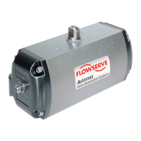
When connecting the motor to alternat-
ing or three-phase current, the diode
(D2) must be bridged: “AC Bridge –
BR1”:
When connecting the motor to direct
current, the jumper “AC Bridge – BR1”
must be removed:
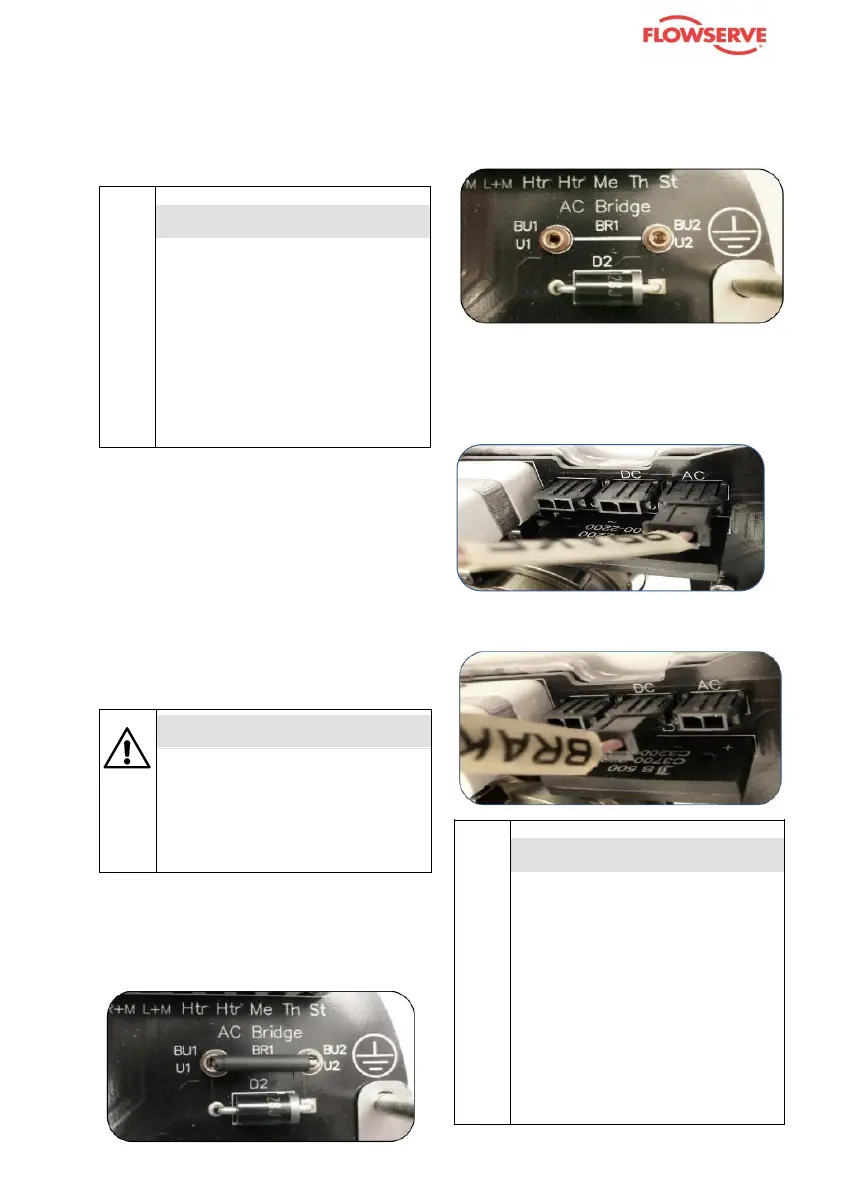
Depending on your available voltage for
the brake (AC or DC) the brake con-
nector must be connected accordingly:
- AC: Insert the “BRAKE” plug in the
AC socket.
- DC: Plug the “BRAKE” connector
into the “DC” connector:
ATTENTION!
A wrong control of the brake
can lead to the motor or/and
brake destruction.
➢ Make sure that the control
system is designed so that
the spring-applied brake is
under tension at the same
time as the motor otherwise
the motor would run against
closed brake.