LTQ008 – LTQ230 Series 3-Phase Products User Instructions – AIIOM000165 EN
Page 10 of 40
3.2 Shipping and Handling
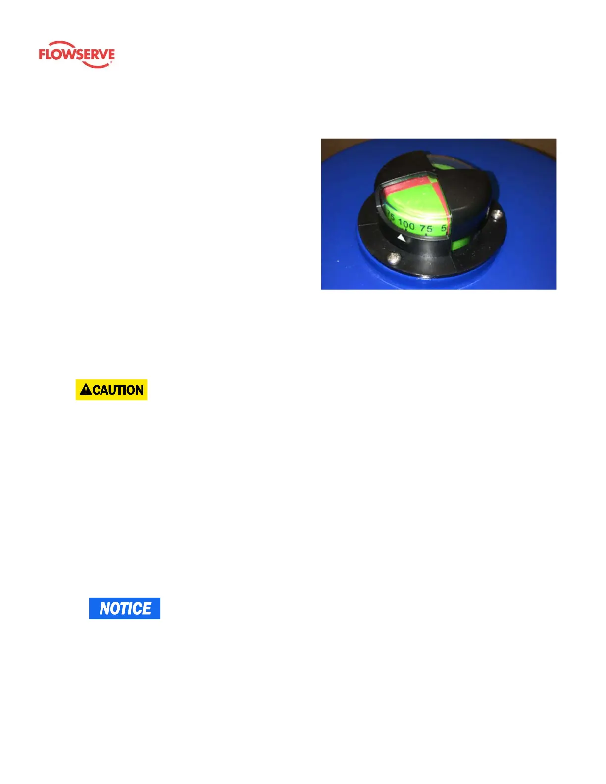
This actuator arrives in the fully CW (0°) position. The red/green position indicator should show all red to denote
this. The actuator has a red and green position indicator on the top of the unit. The red color in the indicator
window means the actuator is fully CW (0°), while the
green color means the actuator is fully CCW (90°). The
indicator has graduations for percent of full travel.
Storage
This unit should not be stored outside unless it is
powered up and has proper conduit terminations.
When not powered up, it should be stored in a clean,
dry environment at all times.
This quarter-turn actuator has been factory tested and
calibrated to operate between 0° and 90°. Most products
will not require recalibration of these settings. If any travel
adjustment is necessary, refer to section 0
Adjustments for instructions.
4 Installation
- Follow the guidelines below for proper installation.
These actuators are designed to be used between a horizontal and upright position. Do not mount the
assembly with the actuator top below a horizontal position (i.e. upside down).
Protect the actuator from moisture by installing it with water-tight, electrical metallic tubing (EMT) fittings
and proper conduit drainage. Supply power to the unit to keep the internal heater warm at the time of
installation (BIC units only).
When installing conduit, use proper techniques for entry into the actuator. Use drip loops to prevent conduit
condensate from entering the actuator.
Mechanical travel stops are factory calibrated for 90° of operation. These stops are not designed to adjust
mechanical rotation by more than ± 3°; they are only for positioning the handwheel.
Use proper equipment on both EMT conduit ports to protect the NEMA 4X integrity of the housing.
Use the internal heater in all applications.
Do not install the actuator outdoors, or in humid environments, unless it is powered up and the heater is
functioning.
Use the proper wire size to prevent actuator failure (see XXX for proper wire sizing).
Terminals 1 – 3 accept 12 – 18 AWG solid / stranded wire. Terminals 4 – N accept 14 – 18 AWG solid /
stranded wire.
- Do not parallel wire, or interconnect controls, from multiple 3 phase actuators. This can
lead to safety bypass, unintentional starting, and potentially damaging operation of the actuator under
power.
Figure 2: Red/green position indicator on top of
actuator