LTQ008 – LTQ230 Series 3-Phase Products User Instructions – AIIOM000165 EN
Page 17 of 40
5.6 Torque Switches
- Torque switches are factory set and are not adjustable. Changing these settings will void the
actuator warranty.
Torque switch operation
The LTQ 008-230 Series actuators have torque switches to protect the actuator, and any attached equipment,
from possible damage that could occur in a high torque event. In such an event, the valve or damper bring
driven encounters some blockage or impediment to travel. In the case of an actuator without torque
switches, the actuator will attempt to drive until it either reaches the end-of-travel or (likely) the motor
overworks and trips on a thermal overload. Units with torque switches will cease supplying power to the motor
when a high torque event occurs.
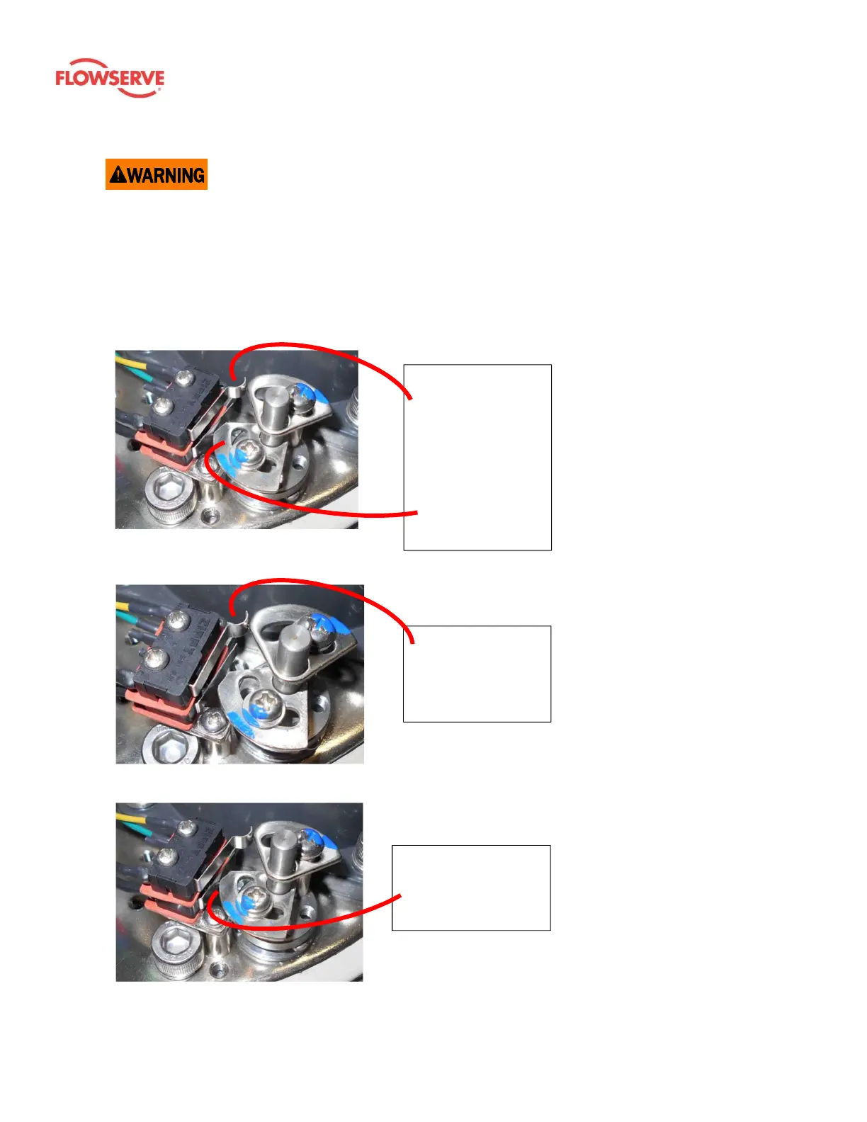
Torque switch – Normal mode
1. In normal operating mode, the
torque switch and drive cam are
in the neutral position shown in
the photo.
2. Internal gearing in-line with the
output drive provide the
rotational action for the cams.
3. The upper torque switch
protects CW rotation.
4. The lower torque switch protects
CCW rotation.
Figure 12: The upper cam is tripping the
upper switch.
Torque Event – CW
1. 12 shows a high torque event in
the CW direction.
2. The torque switch CW drive cam
(upper) and the switch are in
the tripped position.
3. When the torque switch trips, it
immediately cuts off power flow
to the motor for that direction of
travel.
Figure 13: The lower cam is tripping the lower
switch.
Torque Event – CCW
1. Figure shows a high torque
event in the CCW direction.
2. The torque switch CCW drive
cam (lower) and the switch are
in the tripped position.
3. When the torque switch trips, it
immediately cuts off power flow
to the motor for that direction of
travel.
Figure 11: The torque switch cams and
switches are shown in the normal operating
position.
The lower cam has
rotated CW from its
neutral position,
engaging the switch.
The upper cam has
rotated CCW from
its neutral position,
engaging the
switch.
The upper torque
switch and cam for
the actuator drive
the CW rotation.
The lower torque
switch and cam for
the actuator drive
CCW rotation.