LTQ008 – LTQ230 Series 3-Phase Products User Instructions – AIIOM000165 EN
Page 11 of 40
4.1 Installation
- This User Instructions manual references the LTQ008-230 Series
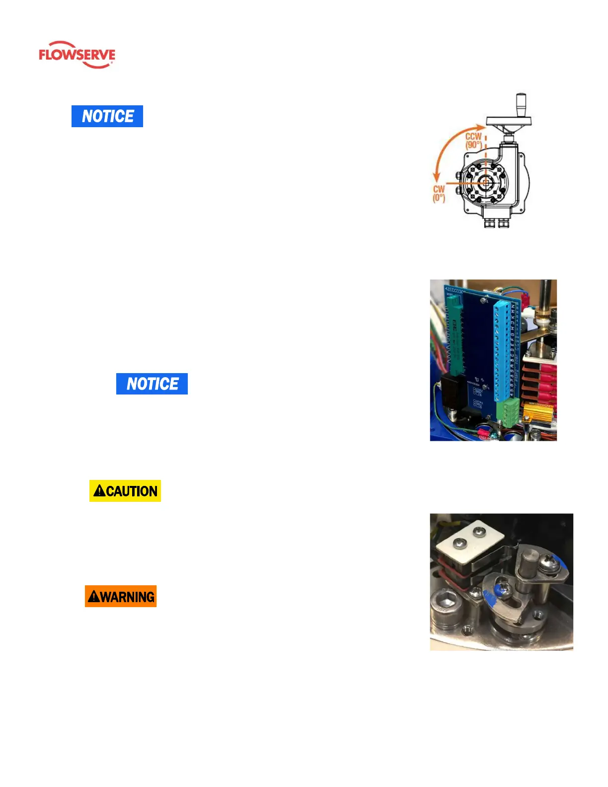
actuator rotation direction while viewed from above the actuator.
All LTQ008-203 Series actuators rotate CW to drive the output shaft (bottom of
the actuator) to the 0° position. On all LTQ008-230 Series actuators, the cam
shaft, and the indicator, rotate CW to 0° as well.
4.2 Mounting
1. Fully close the valve or damper to which the actuator is to be mounted.
2. Assemble the necessary linkage hardware and attach the actuator to the
valve or damper.
3. Center the actuator on the valve or damper drive shaft and tighten all the
hardware.
4. Before applying power to the unit, rotate the manual override handwheel
from the fully CW (0°) to the fully CCW (90°) position to check for
unobstructed manual operation of the valve or damper.
5. The LTQ008-203 Series 3-phase actuators utilize a PCB to simply field wiring
and testing. This PCB contains one of the terminal blocks.
a. The green terminal block is for incoming power, and it contains screw
terminals 1 – 3. It is rated for up to 575V.
- Terminal numbering starts with 1 at the bottom.
b. The blue terminal block contains screw terminals 4 – 9 and A – N which
are rated to accept 14 AWG down to 18 AWG solid or stranded wire.
These are used for interfacing and control wiring.
6. Reference the actuator’s product number and Error! Reference source not
found. to determine which diagram to follow when wiring the actuator.
7. Note that although terminals are labeled as 1 – 9 and A – N, not all terminals
are used on all models.
- Be sure to make field connections to the proper terminal
as identified by the label and not the position.
8. Make the electrical connections per the appropriate wiring diagram for the
actuator.
9. Connect power and control to the correct terminals.
10. Terminals E – N on each actuator are for the auxiliary (adjustable) switches,
which are dry type (volt free) Form A contacts rated for 24V @ 1A Max.
- The torque switches are factory set and are not adjustable.
Torque switches protect controlled valves or actuators from damage in the
event of a high torque condition.
Figure 3: Note that the
rotation seen from below is a
mirror of the direction viewed
from above.
Figure 4: Printed circuit
boards (PCB) contain the
terminal block. They
facilitate simple field
wiring and testing.
Figure 5: A torque switch (TS)
is a secondary set of cams
(switches) which further
protects the actuator,
equipment, and processes.