LTQ008 – LTQ230 Series 3-Phase Products User Instructions – AIIOM000165 EN
Page 29 of 40
7.2 Calibration Procedure for BIC Proportional Control
- Allowing the motor to drive the gear train into the mechanical stop will result in severe
damage to the actuator! Remove power from this device before making any travel adjustments.
After completing all mounting and wiring procedures, and main power is available, it is now possible to
commission the actuator. Before applying power or making any wiring connections:
1. Remove 3 phase power.
2. Set the DIP switches for correct signal IN and OUT. (ref 5 pos DIP)
3. Set the DIP switches for correct signal response and loss of signal action. (ref 4 pos
DIP)
4. Apply correct power according to the actuator model.
5. The blue LED D1 (ref POWER LED) will turn on, and green LED STA will turn on. (ref
CPU RUNNING)
6. Press the “SET” black pushbutton on the Mod control board and hold it down for
about three seconds, then release
a. The green STA LED will turn off and the unit will drive to the fully CW position and
stop when the pre-set cam positions are reached.
b. There are NO LED indicators to advise when the actuator is running. – 2 teeth CW
before tightening the two M3 set screws on the sector drive gear.
7. When the actuator stops, press the CLO pushbutton ONCE.
a. The actuator will drive to its full CCW (Open) position and stop when the pre-set cam positions are
reached.
8. When the actuator stops, press the OP
pushbutton ONCE.
9. The unit will start to respond to the incoming
analog control signals being sent to the
actuator.
10. Slight adjustments may be made to trimmer VR2
if necessary, to tune the feedback signal (20mA
end of scale only).
11. Unit is now calibrated and is ready to be put into
service. No other calibration is necessary.
Figure 29
the sector and
potentiometer gear
sets at the fully CW
position (see step 8).
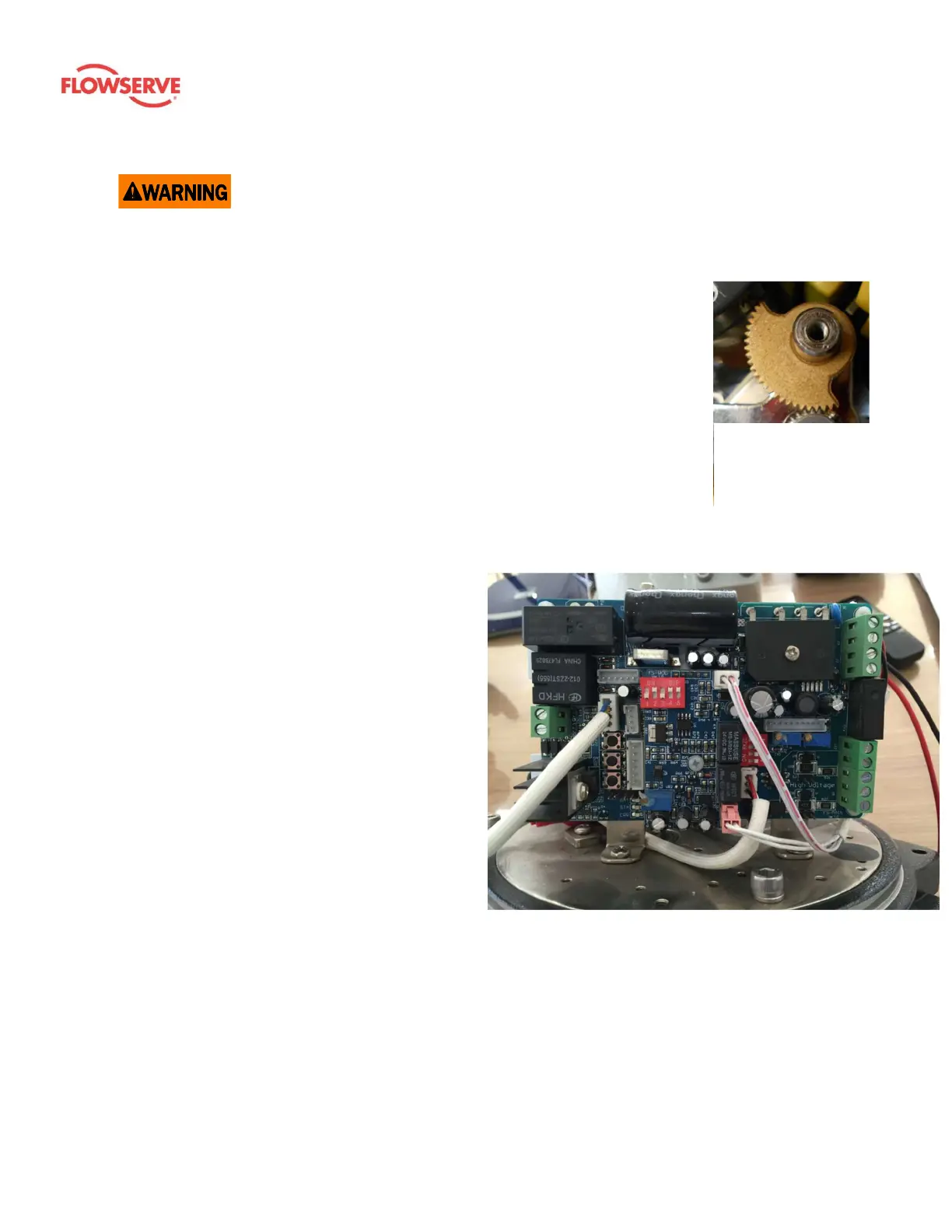
Figure 30: Proportional PCB 3-phase (24 V controller)