IX
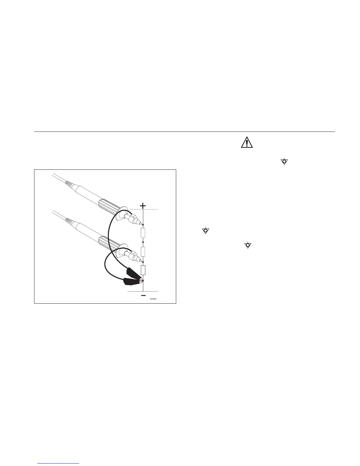
The ScopeMeter test tool uses a three-lead connection sys-
tem for dual input, isolated (electrically floating) measure-
ments. The connections for isolated and grounded
measurements are shown in the following illustration.
Figure 1. Common (Ground) Connections
WARNING
DO THE FOLLOWING TO AVOID ELECTRICAL SHOCK
IF A SCOPEMETER TEST TOOL
COM (COMMON)
INPUT IS CONNECTED TO >42V PEAK (30V RMS):
1. USE ONLY THE TEST LEAD/PROBE SET SUPPLIED
WITH THE SCOPEMETER TEST TOOL (OR
SAFETY-DESIGNED EQUIVALENTS WITHOUT
EXPOSED METAL CONNECTORS).
2. DO NOT USE CONVENTIONAL EXPOSED METAL
BNC OR BANANA PLUG CONNECTORS IF THE
COM (COMMON) IS >42V PEAK (30V RMS).
3. USE ONLY ONE COM (COMMON) CONNECTION
(THE 4-MM BLACK BANANA JACK).
4. REMOVE ALL PROBES AND TEST LEADS THAT
ARE NOT IN USE.
5. USE 600V RATED PROBE TIP ADAPTERS.
"600V" IS PRINTED ON EQUIPMENT SO RATED.
6. CONNECT THE PM8907 POWER ADAPTER TO THE
AC OUTLET BEFORE CONNECTION TO THE
SCOPEMETER TEST TOOL.