Calibration Adjustment
4.6 Final Calibration 4
4-9
Table 4-2. HF Gain Calibration Points Slow
Cal step 5500A Setting
(1 kHz, MODE
wavegen,
WAVE square)
Test Tool Input Signal
Requirements
(1 kHz square, t
rise
<2 μs,
flatness after rising edge:
<0.5% after 4 μs)
HF-Gain AB (CL 0609) 25V 25V
HF-Gain A (CL 0612),
HF-Gain B (CL 0632)
HF-Gain A (CL 0615), HF-Gain B (CL 0635)]
1)
50V 50V
1)
After starting the first step in this table cell, these steps are done automatically.
4.6.2 Delta T Gain, Trigger Delay Time & Pulse Adjust Input A
Proceed as follows to do the calibrations:
1. Press
to select calibration step Delta T (CL 0700):IDLE
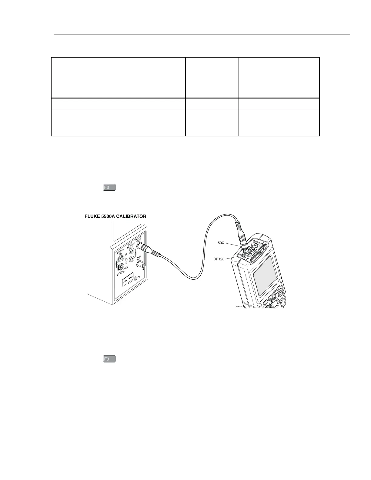
2. Connect the test tool to the 5500A as shown in Figure 4-4.
ST8004.WMF
Figure 4-4. 5500A Scope Output to Input A
3. Set the 5500A to source a 1V, 1 MHz fast rising (rise time ≤ 1 ns) square wave
(SCOPE output, MODE edge).
4. Set the 5500A to operate (OPR).
5. Press
to start the calibration.
The Delta T gain, Trigger Delay (CL0720), and Pulse Adjust Input A (CL0640) will
be calibrated.
6. Wait until the display shows Pulse Adj A (CL 0640):READY.
7. When you are finished, set the 5500A to Standby.
8. Continue at Section 4.6.3.

 Loading...


