Insulation Testers
Performance Tests
17
Performance Tests
The following series of tests comprise a performance test for verifying the accuracy of
the Meter (UUT) and its performance level. The performance test is recommended as an
acceptance test for incoming inspection and as a calibration procedure for periodically
ensuring the accuracy of the Meter. Fluke recommends running the performance test at
least once a year.
No adjustments are required during the performance test, and it is not necessary to open
the case. If the Meter does not pass all parts of the performance tests, repair and/or
calibration adjustment are required. A calibration adjustment procedure is given later in
this manual. If significant repairs are required, contact Fluke as described toward the
front of this manual. If user repairs are appropriate, refer to the list of user-replaceable
parts toward the end of this manual.
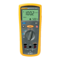
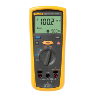
Testing the Voltage Function
To verify the accuracy of the voltage measuring function, do the following:
1. Turn the UUT rotary switch to the
V function.
2. Connect the Calibrator to the
INSULATION and COM terminals of the UUT.
3. Apply the input level for each step listed in Table 3.
4. Compare the reading on the UUT display with the Display Reading in Table 3.
5. If the display reading falls outside of the range shown in Table 3, the Meter does
not meet specification.
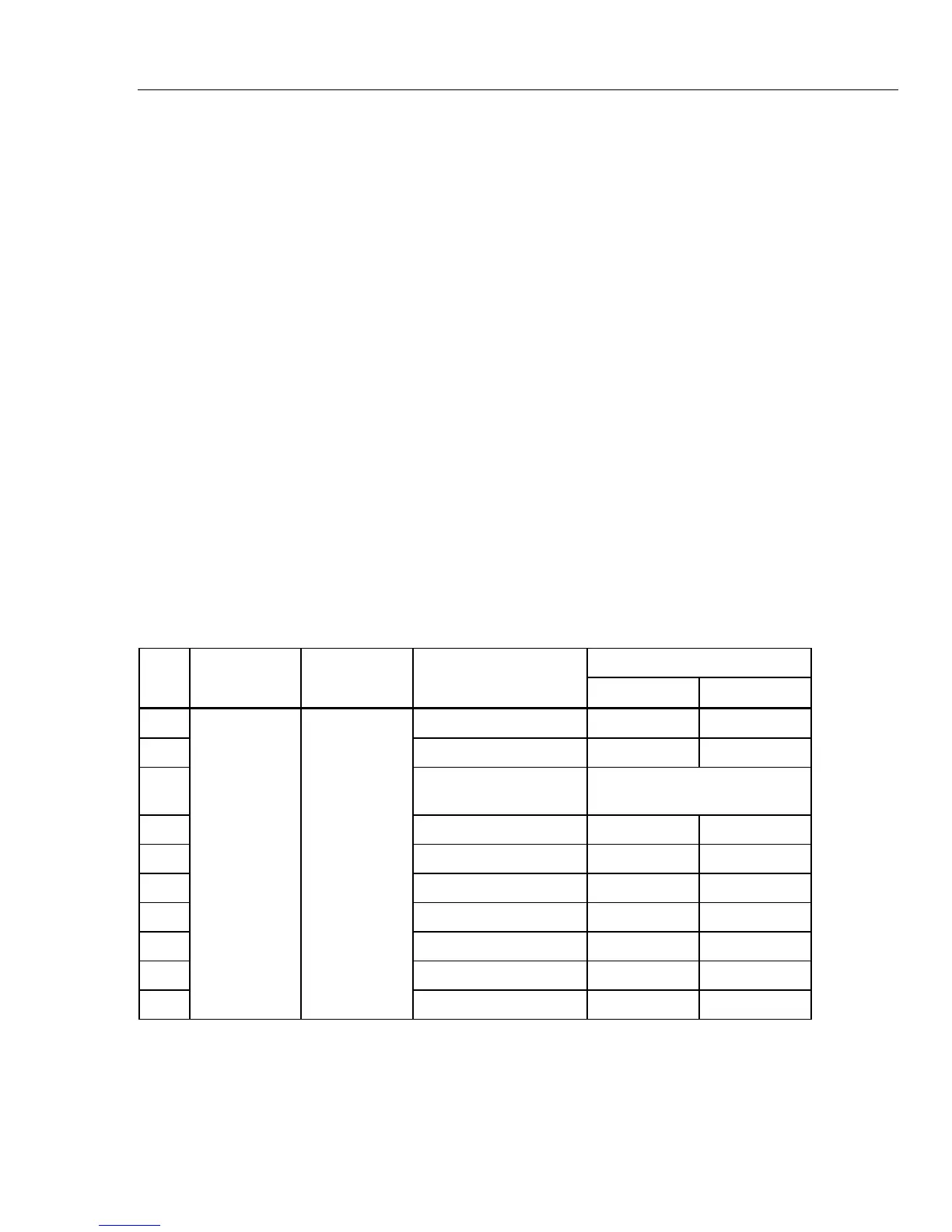
Table 3. Voltage Accuracy Tests
Display Reading
Step Function Range Applied Input
Low Limit High Limit
1. 400 mV, 0 Hz 0.1 0.7
2. 8 V, 0 Hz 7.5 8.5
3.
8 V, 400 Hz Display must show V ac
annunciator
4. 50 V, 0 Hz 48.7 51.3
5. 100 V, 0 Hz 97.7 102.3
6. 250 V, 0 Hz 244.7 255.3
7. 500 V, 0 Hz 489.7 510.3
8. 120 V, 60Hz 117.3 122.7
9. 230 V, 50 Hz 225.1 234.9
10
V 600.0 V
645 V, 400 Hz, 631.8 658.2
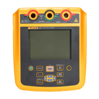
Discharge Circuit Test
The following Discharge Circuit Test is a safety related test that verifies input jack wiring
to the PCA, the RSOB contacts, RSOB PCA pads, and other active discharge components
on the PCA.
1. Place a Shorting Bar across the UUT
COM and INSULATION input terminals.
Downloaded from Elcodis.com electronic components distributor
 Loading...