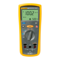
Insulation Testers
Performance Tests
25
Table 7. I Nominal Test/Limit Test
Step Function Range Applied Load DMM Display Reading
1. Insulation 1000 V 1 MΩ
2. Insulation 500 V 500 kΩ
3. Insulation 250 V 250 kΩ
4.
Insulation
(1507/1508)
100 V 100 kΩ
>1000
Remove the Calibrator and apply a separate 50 kΩ resistor for the following test
5.
Insulation
(1507/1508
50 V 50 kΩ >1000
I Limit Test:
The following test verifies the UUT’s internal insulation function and current limit
operation.
1. Connect the DMM and 50-kΩ resistor to the UUT
INSULATION and COM
terminals as shown in Figure 8.
2. Set DMM function switch to µADC.
3. Set the UUT rotary switch to the 1000 V range.
4. Press and hold the T key.
5. The DMM reading should be <2000.0 µA.
Testing the “Ω” Function
Earth Bond Resistance Accuracy Tests
To test earth bond resistance accuracy, complete the test steps in Table 8, using the
following procedure.
1. Connect the UUT
COM and Ω terminals to the calibrator.
2. Set the calibrator to the Ohms function.
3. Turn the UUT rotary function switch to the Ω function.
4. Apply the calibrator output for Steps 1-3.
5. Press the T key, and verify that the UUT reading is within the display
reading limits shown in Table 8.
6. Apply a separate 2-Ω precision resistor directly to the UUT
Ω and COM
terminals using the shortest leads possible to minimize lead resistance, or press
the blue key to zero out the test leads prior to connecting to the resistor.
7. Press T, and verify that the reading is within the display reading limits for
Step 4.
Downloaded from Elcodis.com electronic components distributor

 Loading...