150X Series
Calibration Manual
20
Calibrator
M
IN
M
A
X
H
O
L
D
RE
L
%
m
s
H
z
R
A
N
GE
dB
d
B
a
c
+
dc
a
c
+d
c
a
c
+
d
c
ac+
dc
F
n
S
mA
mA
A
mV
V
V
O
F
F
C
A
A
A
A
m
A
C
OM
V
T
E
M
P
E
R
A
T
U
R
E
A
a
c
+d
c
Au
toHO
LD
LO
GGING
S
A
V
E
C
ANCE
L
Y
ES
NO
C
L
E
AR
M
E
M
V
IE
W
S
ETU
P
sHi sLo
Hi Lo
I+ I-
!
1
23
456
789
0
Ñ
E
OFF
ON Mode
Aux
Hz
Ω
A
V
A B C D E F CLR
GH I J KL
MN OP QR
ST UV WX
YZ
OUTPUT
1500Vpk
max
15Vpk
max
15Vpk
max
HIGH VOLTAGE
DANGER
_
/
!
189
LOGGING MULTIMETER
50 k
9 G
mV
ecz16f.eps
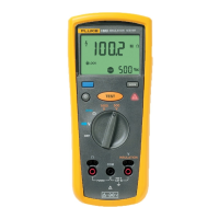
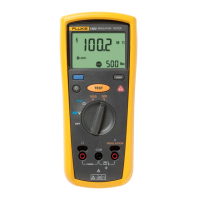
Figure 6. 9-GΩ Resistor Verification
5 % of Full Scale, Insulation Resistance Accuracy Test, 50 V Range (Models 1507 and
1508)
The following test verifies the minimum insulation resistance accuracy, of the 50 V
range, using a separate 50-kΩ resistor.
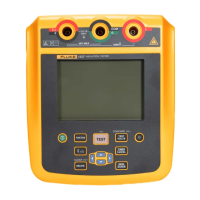
1. Connect a 50-kΩ, +-0.1%, 0.25 W, 25 PPM resistor to the UUT
INSULATION
and
COM terminals.
2. Turn the UUT rotary function switch to the 50 V insulation range.
3. Press the UUT T key.
4. Verify that the Meter display reading is within the Limits of 0.00 and 0.10.
Insulation Function, External Sense
The following test verifies that the Meter will sense a voltage >30 V when present on the
circuit under test.
1. Connect the UUT
INSULATION and COM output terminals to the calibrator
voltage output terminals.
2. Turn the UUT rotary function switch to an insulation function.
3. Apply 35 V, 50 Hz to the UUT.
4. Verify that the UUT displays >30 V in the primary display, and the red LED
lightning bolt comes on.
Downloaded from Elcodis.com electronic components distributor
 Loading...