Insulation Testers
Performance Tests
21
Source Voltage Accuracy Test, "R" Nominal
Complete the test steps in Table 5 to verify source voltage of the insulation function
under load.
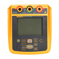
1. Connect the test DMM and calibrator in parallel to the UUT
INSULATION and
COM terminals. See Figure 7.
2. Put the calibrator in the insulation test function.
3. Set the calibrator for the applied load shown in Table 5 for Steps 1-4.
WCaution
To avoid overranging the test DMM, a HV Divider must be used
in conjunction with the DMM for testing the 1000 V range.
4. Press T and verify that the UUT and Test DMM voltage readings are
within the limits of Table 5. Record both of these readings.
5. Replace the calibrator with a separate 50-kΩ resistor.
6. Press T and verify that the UUT display reading and DMM display.
reading are within the limits of Table 5 for Step 5. Record both of these readings.
7. Using the DMM reading as the reference, calculate the UUT voltage reading
error %, (DMM V - UUT V / DMM V) x 100, and record for later use.
Table 5. Source Voltage Accuracy Test, R-Nominal
Step
UUT
Function
Meter
Range
Applied
Load
DMM Display
Reading
UUT Display
Reading
UUT Voltage
Reading Error %
1. Insulation 1000 V 1 MΩ 1000 V to 1200 V 1000 V to 1200 V
[1]
2. Insulation 500 V 500 k 500 V to 600 V 500 V to 600 V
3. Insulation 250 V 250 kΩ 250 V to 300 V 250V to 300 V
4.
Insulation
(1507/1508)
100 V 100 kΩ 100 V to 120 V 100 V to 120 V
Remove the Calibrator and apply a separate 50 kΩ resistor for the following step.
5. Insulation
(1507/1508)
50 V 50 kΩ 50 V to 60 V 50 V to 60 V
[1] Must use HV divider with DMM for this reading.
Downloaded from Elcodis.com electronic components distributor
 Loading...