150X Series
Calibration Manual
26
Table 8. Earth Bond Resistance Tests
Display Reading
Step Meter Range Applied Display Units
Low Limit High Limit
1. 2000 Ω 810.0 Ω Ω 795 825
2. 2000 Ω 990.0 Ω Ω 972 1008
3. 20.00 KΩ 18.0 kΩ kΩ 17.70 18.30
Remove calibrator and apply a separate 2 Ω resistor for the following step.
4. 20.00 Ω 2.0 Ω Ω 1.94 2.06
2-Ohm Output Current Test
The following procedure verifies the minimum current for a 2-Ω Load in continuity
function.
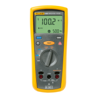
1. Connect a 2-Ω resistor and DMM to the UUT as shown in Figure 9.
2. Set the DMM rotary function switch to the mVDC function.
3. Set the UUT rotary function switch to the Ω function.
4. Press the T key and record the DMM voltage reading.
5. Using Ohms Law (V = I x R where: V = Voltage, I = Current, and R =
Resistance), calculate the current through the 2-Ω resistor.
6. The current should be greater the 200 mA.
M
IN
M
A
X
H
OLD
R
E
L
%
m
s
H
z
R
A
N
GE
dB
d
B
a
c
+
dc
a
c
+
d
c
ac
+
d
c
a
c
+
dc
F
n
S
m
A
m
A
A
m
V
m
V
V
V
O
F
F
C
A
A
A
A
m
A
C
O
M
V
T
E
M
P
E
R
A
T
U
R
E
A
a
c+
dc
A
utoHOLD
LOGGING
SAVE
CANCEL
YES
NO
C
L
EA
R
M
E
M
V
IE
W
SETUP
189
LOGGING MULTIMETER
INSULATION TESTER
1507
2
I =
E
R
mV
ecz14f.eps
Figure 9. 2-Ω Output Current Test
Downloaded from Elcodis.com electronic components distributor
 Loading...