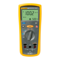
Insulation Testers
Performance Tests
19
Table 4. Insulation Resistance Accuracy Test
Display Reading Limits
Step
Insulation
Voltage Range
Applied Display Units
1503 1507/1508
1. 1000 V 1.9 GΩ 1862 to 1938 n/a
2. 1000 V 1 MΩ 0.5 to 1.5 0.5 to 1.5
3. 1000 V 49 MΩ 47.5 to 50.5 47.8 to 50.2
4. 1000 V 60 MΩ 58.3 to 61.7 58.6 to 61.4
5. 500 V 500 kΩ 0.44 to 0.56 0.44 to 0.56
6. 250 V 250 kΩ n/a 0.20 to 0.30
7. 100 V 100 kΩ
MΩ
n/a 0.6 to 0.15
Full-Scale Insulation Resistance Accuracy Test, 1000 V Range (Models 1507 and 1508)
The following test verifies the full-scale accuracy of the 1000 V range using a separate
9-GΩ resistor. Prior to performing the accuracy test, verify that the 9-GΩ resistor is
within specifications as follows:
9-GΩ Resistor Test
1. Make a divider network using a certified precision 50-kΩ resistor (within
+/- 0.1% accuracy) in series with the 9-GΩ resistor.
2. Connect the calibrator and UUT to the resistor divider as shown in Figure 6.
3. Set the UUT to the mV function.
4. Set the output of the calibrator to 1000 V.
5. Check that the UUT reading is within 5.34 to 5.66 mV.
6. Set the calibrator for 0 V output and remove the calibrator from the divider
network.
Accuracy Test
1. Remove the 50-kΩ resistor from the divider.
2. Connect the 9-GΩ resistor to the UUT
INSULATION terminals.
3. Turn the UUT rotary function switch to the 1000 V range.
4. Push the T key and verify that the display reading is within the limits of
7.8 to 10.2 GΩ.
Downloaded from Elcodis.com electronic components distributor

 Loading...