1773/1775/1777
Calibration Manual
6
Equipment Assembly
The 17xx calibration cables and verification box are not available from Fluke. If you plan to
calibrate your Product rather than send it to a Fluke Service Center, use the assembly
instructions that follow.
Note
The 17xx calibration cables are identical and the verification box is similar to the
previous 173x/174x calibration equipment.
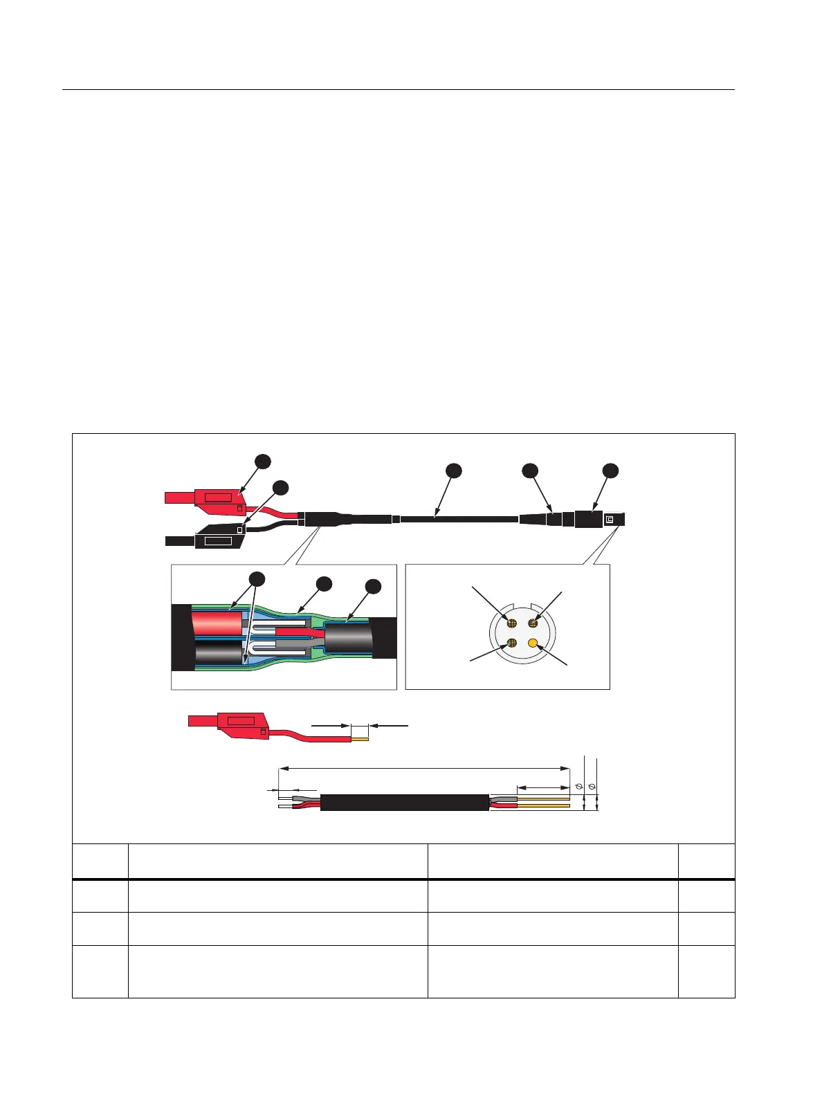
17xx Calibration Cable Assembly
See Ta b l e 3 for instructions on how to make the calibration cables.
W Caution
Cable must be marked with “max. 30 V to earth.” Remove any voltage-, category-,
or current-ratings on safety plugs.
Table 3. 17xx Calibration Cables, Voltage-to-Current-Input
Item Description Part Number/Info QTY
Straight Plug, IP50, 4-Pole ODU: S21M08-P04MJG0-528S 1
Cable Bend Relief ODU: 701-023208965-040 1
Signal-Cable, 2x AWG 22-24, shielded
∅4-5 mm
(Fluke equiv. # 3803634)
1
10
+
2
0
1930
±10
15
±1
4
-
0
1
5 max.
4 min.
Screen
(Pin 4)
N.C.
(Pin 3)
Red Wire
(Pin 1)
Black Wire
(Pin 2)

 Loading...