3 Phase Power Quality Analyzer
Setup
9
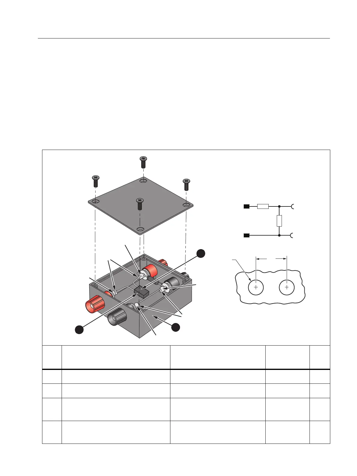
Verification Box Assembly
This Verification Box provides more accurate voltages than a direct connection to the 5520A. The
5520A uses a divider with a 50 Ω output impedance when sourcing <330 mV. Due to variations in
the Analyzer input impedance, the actual applied voltage is less than the programmed voltage.
Using an external divider where the parallel resistance is ~30 Ω allows calculation of the applied
voltage with confidence that the Analyzer input loading will not significantly impact the applied
voltage.
Fluke recommends using a verification box that has a divider with 30 Ω across the Analyzer input
and 10 kΩ in series with high side of the input. See Tab le 5 for instructions on how to make the
verification box.
Table 5. 17xx Verification Box
Item Description Part Number/Info
Fluke
Part Number
QTY
Plastic Box: 2.69 in L x 1.82 in W Pomona: 3850-0 1924576 1
Binding Post, Black Pomona: 4243-0 1633063 2
Resistor, Metal Foil 10 kΩ,
±0.1 %, 0.6 W, ±4.5 PPM
Red Plug/Red Socket 2114858 1
Resistor, 30 Ω, 1 W, 1 % 20 PPM
Red Socket/Black Socket +
Bridge Black Plug/Socket
1757740 1
2
3
2
1
Contacts Pretinned
Contacts
Pretinned
Red
Plug
Red
Socket
Black
Socket
Black
Plug
Soldered
Soldered
Soldered
Soldered
10 k
30
Ω
Red
Black Black
Red
.375
(9.53)
Panel Cutout
.750
(19.05)
V
in
V
out

 Loading...