3 Phase Power Quality Analyzer
Setup
7
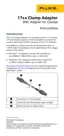
17xx AUX Input Calibration Cable
See Ta b l e 4 and Figure 2 for instructions on how to make the calibration cable.
W Caution
Cable must be marked with “max. 30 V to earth.” Remove any voltage-, category-,
or current-ratings on safety plugs.
Item Description Part Number/Info QTY
Test Lead with 4 mm Safety Plug,
stackable
red 1
Test Lead with 4 mm Safety Plug,
stackable
black 1
Heat Shrink Tubing, 2:1 ∅=4.8 mm (3/16”); L=35 mm 3
Heat Shrink Tubing, 3:1, adhesive ∅=12 mm (1/2”); L=60 mm 1
Table 4. 17xx AUX Input Calibration Cable
Item Description Part Number/Info QTY
Binder: Series 620 - Male Cordset, 4-pole, 2 m Binder: 79 9241 020 04 1
Test Lead 0.75 mm² with 4 mm Banana Plug,
stackable
red 2
Test Lead 0.75 mm² with 4 mm Banana Plug,
stackable
black 2
Shrink tube Ø 5-6 mm, black, thin wall, 3:1 L = 30 mm 4
Shrink tube Ø 8-10 mm, transparent, thin wall,
2:1
L = 45 mm 2
Shrink tube Ø 10-12 mm, black, thin wall,
adhesive, 3:1
L = 30135 1
Shrink tube Ø 12-14 mm, black, thin wall, 3:1 L = 110 mm 1
Table 3. 17xx Calibration Cables, Voltage-to-Current-Input (cont.)

 Loading...