3 Phase Power Quality Analyzer
Accuracy Verification Procedure
15
5. Do this for all ranges in Ta b l e 9 :
a. Set the calibrator to supply a 57.0 Hz sine wave for all voltages.
b. Wait until each reading has stabilized.
The Calibration Tool is the first choice for readings because the resolution is higher than
the instrument UI. If this is not available, select PQ Meter from Home menu to see the
voltage readings.
6. When you are done, set the calibrator to Standby.
Voltage Transient Measurement
This verification is required on the 1775 and 1777 models only.
To measure transient voltage:
1. Select the setup. See Basic Instrument Setup for all Verifications.
2. Make sure the Analyzer is on battery power with ≥50 % charge.
3. Connect the single test lead Earth to the calibrator NORMAL LO.
4. Use the 552xA or 57x0A calibrator to:
a. Connect the calibrator NORMAL V output to the 3PHVL-1730 L1+L2+L3+N leads.
b. Connect the calibrator NORMAL V output to the V input of the reference DMM.
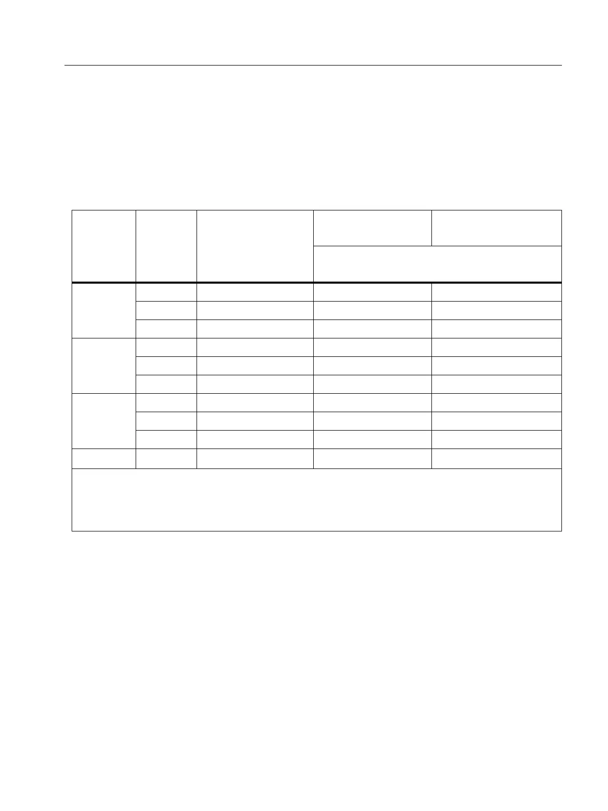
Table 9. Voltage Verification
Declared
Input
Voltage
U
din
[1]
Range
Calibrator Voltage
57 Hz sine wave
Minimum Reading
-0.1 % of U
din
Maximum Reading
+0.1 % of U
din
for 10 % to 150 % of supported U
din
:
± (0.1 % of U
din
), otherwise 0.1 % of range
120 V
1000 V 12 V 11.88 V 12.12 V
1000 V 120 V 119.88 V 120.12 V
1000 V 180 V 179.88 V 180.12 V
230 V
1000 V 23 V 22.77 V 23.23 V
1000 V 230 V 229.77 V 230.23 V
1000 V 345 V 344.77 V 345.23 V
480 V
1000 V 48 V 47.52 V 48.48 V
1000 V 480 V 479.52 V 480.48 V
1000 V 720 V 719.52 V 720.48 V
690 V 1000 V
1000 V
[2]
999.31 V 1000.69 V
[1] In the power quality standard IEC 61000-4-30, the declared input voltage U
din
determines the accuracy
requirements of voltages from 10 % to 150 % of U
din
. For measurements in low voltage mains supplies, U
din
is identical to the nominal supply voltage, for example 120 V or 230 V.
[2] The test voltage is limited by the maximum output voltage of the calibrator. According to IEC 61000-4-30 the
150 % test voltage is 1035 V.

 Loading...