1773/1775/1777
Calibration Manual
18
AUX Input Check
To check the AUX input:
1. Connect 173x/174x AUX input calibration cable to the Analyzer AUX inputs.
2. Stack the two red banana plugs together and connect them to the calibrator Normal HI.
3. Stack the two black banana plugs together and connect them to the calibrator Normal LO.
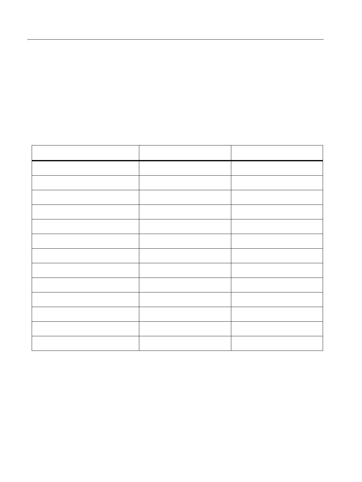
4. For each voltage in Ta b l e 1 2 , set the calibrator and check that the values are between the
limits.
5. Set the calibrator to Standby.
Table 12. AUX Input Verification
Calibrator Out DC Volts Lower Limit Vdc Upper Limit Vdc
-10.0000 -10.025 -9.975
-5.0000 -5.015 -4.985
-1.0000 -1.007 -0.993
-0.5000 -0.506 -0.494
-0.1000 -0.1052 -0.0948
-0.0100 -0.01502 -0.00498
0.00 -0.005 0.005
0.0100 0.00498 0.01502
0.1000 0.0948 0.1052
0.5000 0.494 0.506
1.0000 0.993 1.007
5.0000 4.985 5.015
10.0000 9.975 10.025

 Loading...