Introduction and Specifications
Front-Panel Features 1
1-11
Table 1-4. Front-Panel Features (cont.)
Item Description
Mains Power Switch
The power switch turns the power on and off. The switch is a latching push-push type. When the
switch is latched in, power is on.
Note
The front panel power switch operates electronically and is not an
isolation switch. The main power ON/OFF isolation switch is on
the rear panel.
Chassis ground connection
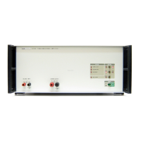
Input Terminals
Used to input voltage or current to the Product.
A V
Sets the INPUT to receive voltage or current.
INPUT OVER RANGE Indicator
Comes on when the input exceeds the limit.
O N
Sets LCOMP on or off. LCOMP ON is used for highly inductive loads. See the Specifications for
inductive loading limits.
L
Sets the Product for local (front panel) control when it is in remote mode.
D C B
Sets the output range to 2, 20, or 120 amps.
H K
Puts the output current on the High Current or Low Current output terminals.
OPTION POWER OUTLET
BNC connector that sources 12 V dc to power the cooling fan of a connected accessory such as a
25 turn coil.
LOW Current Output Terminals
Used with 2 A and 20 A output ranges.
HIGH Current Output Terminals
Used with all output ranges.