52120A
Users Manual
1-10
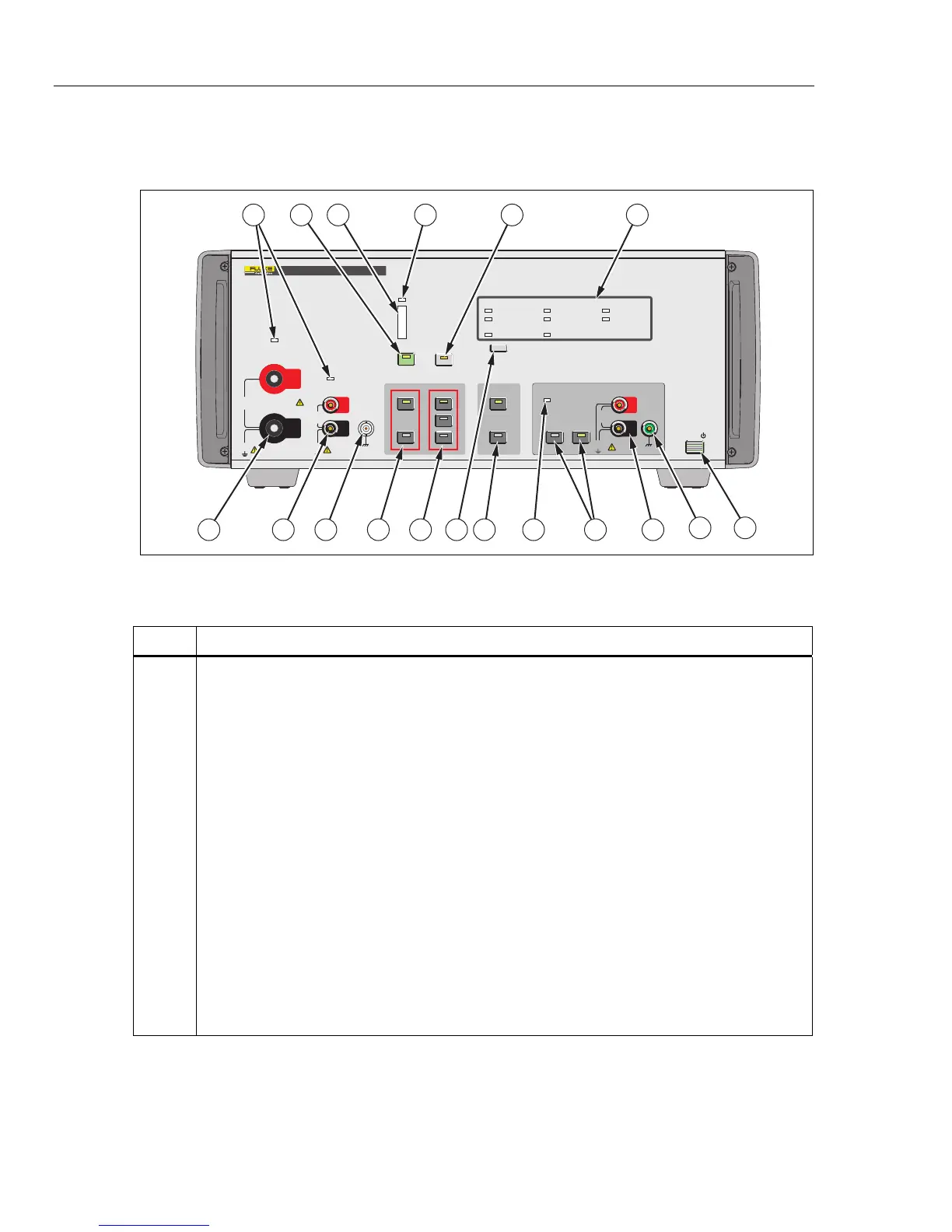
Front-Panel Features
Table 1-4 is a list of front-panel controls and connections shown in Figure 1-1.
20A
120A
ON
OFF
VOLTS
AMPS
HIGH
LOW
2A
LOCAL
STBY
OPR
3V PK
300mA PK
MAX
HIGH CURRENT
OUTPUT
LOW CURRENT
OUTPUT
850V PK
MAX
850V PK
MAX
30A PK
7V PK
MAX
180A PK
7V PK
MAX
OUTPUT
TERMINALS RANGE
VOLTAGE
COMPLIANCE
MAX
OVER COMPLIANCE
MIN
STATUS
MASTER UNIT
SLAVE UNIT
REMOTE OVER TEMP
L2 PHASE
L1 PHASE L3 PHASE
N PHASE
INPUT
INPUT OVER RANGE
L COMP
POWER
10V PK
MAX
OPTION
POWER
OUTPUT
(12V DC)
52120A
TRANSCONDUCTANCE AMPLIFIER
HI
LO
HI
LO
HI
LO
43 6
78
913 1112161718
52
10
1
1415
gpp001.eps
Figure 1-1. Front-Panel View
Table 1-4. Front-Panel Features
Item Description
Current Output Indicators
Output on indicator. In STBY (standby) mode, these two indicators will be Amber. In OPR
(operate) mode, the indicator for the selected terminals will be illuminated green.
M
The OPR (Operate) key places the Product in operate mode. Operate mode is indicated by the lit
indicator on the OPR key. The indicator over the set output terminals also shows green.
Voltage Compliance Level Indicator
Over Compliance Indicator
Indicates when the Product senses the voltage developed across the current terminals due to the
current through the load impedance has exceeded the specified level. This condition also
automatically puts the Product in standby to remove the output current.
S
The STBY (Standby) key puts the Product in standby mode. Standby mode is indicated by the lit
indicator on the STBY key. The output indicators above the output terminals also shows amber.
Status Indicators
Indicates the status of the different functions of the Product.