Calibration
Introduction 5
5-23
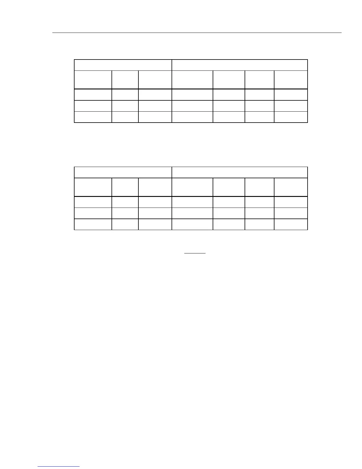
Table 5-9. Power Line Frequency Confidence Check Points
6105A Measured Accuracy
Range RMS
Phase
Angle (∅)
V I I + Limit I - Limit
1 x Ext 2A 2 A 60° 2.000280 1.99720
1 x Ext 20A 20 A 60° 20.00280 19.99720
1 x Ext 120A 120 A 60° 120.0168 119.9832
Phase Angle Accuracy Confidence Check
To do a phase angle accuracy confidence check, set the range, rms, and phase angle of
the 6105A to the values in Table 5-10.
Table 5-10. Phase Angle Accuracy Confidence Check Points
6105A Measured Accuracy
Range RMS
Phase
Angle (∅)
Phase Angle
Error (∅)
PF VA Watts
1 x Ext 2A 2 A 60°
1 x Ext 20A 20 A 60°
1 x Ext 120A 120 A 60°
To calculate phase angle from PF or VA and watts:
PF =
Watts
VA
error(∅) = cos
–1
(PF) –
θ
For example, if the power meter shows PF = 0.499894:
error(∅) = cos
–1
(0.499894) – 60 = 0.007°
Verify Amplitudes at DC and Higher Frequencies
Use the Fluke A40B and 8508A to verify amplitude accuracy.
2 Amp Range
1. Set the DMM to DCV function on the 2 V range.
2. Set the DMM ‘m’ store to the 2 A shunt correction factor.
3. Set the DMM ‘-c’ and ‘÷z’ stores to 0.4.
4. Turn on the ‘*m’, ‘-c’ and ‘÷z’, and % math functions on the DMM.
5. Set the 6105A range to 1 x Ext 2A.
6. Set the current and frequency of the 6105A to the values in Table 5-11 for the 1 A
verification point.
7. Set the DMM ‘-c’ and ‘÷z’ stores to 0.8.
8. Set the DMM to ACV function.
9. Set the current and frequency of the 6105A to the values in Table 5-11 for the two
2 A verification point.