Introduction and Specifications
Input and Output Connections 1
1-13
Table 1-5. Rear-Panel Features (cont.)
Item Description
The CALIBRATION ENABLE / NORMAL switch is used to write enable and disable the
nonvolatile memory that stores calibration constants. See the Calibration section of this
Manual to learn more about calibration of the Product. Set to NORMAL for normal
operation.
The AUXILIARY PROTECTIVE terminal is internally grounded to the chassis.
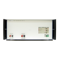
Mains Power Receptacle
Grounded three-prong connector that accepts the line power cord.
Fuse Holder
Holds the mains power fuse. See the Maintenance section for the fuse replacement
procedure.
Input and Output Connections
W Caution
To prevent damage to the Product, do not connect mains power
to any signal input or output terminal.
Input Terminals
The input terminals of the Product are 4 mm binding posts. Table 1-6 shows the
maximum voltage and current that can safely be applied to the input terminals.
W Caution
To prevent damage to the Product, do not apply voltage
between the HI and LO input terminals when input current is
set. This can cause the burden resistor to change its resistance
value and invalidate the calibration for current input.
Table 1-6. Maximum Voltage and Current on Input Terminals
Output Current
Range
Maximum Voltage
Input HI and LO
Maximum Current
Input HI to Lo
Maximum Voltage
HI or LO to Earth
2 A and 20 A 2 V rms, 3 V pk 200 mA rms 30 V pk
120 A 1.2 V rms, 1.7 V pk 120 mA rms, 170 mA pk 30 V pk
When the input terminals are configured for current input, a precision burden resistor is
connected across the HI and LO terminals to make a voltage from the input current.
The green 4 mm binding post is connected to the chassis of the Product. This is a signal
connection and must not be used for a protective earth connection.