Calibration
Introduction 5
5-11
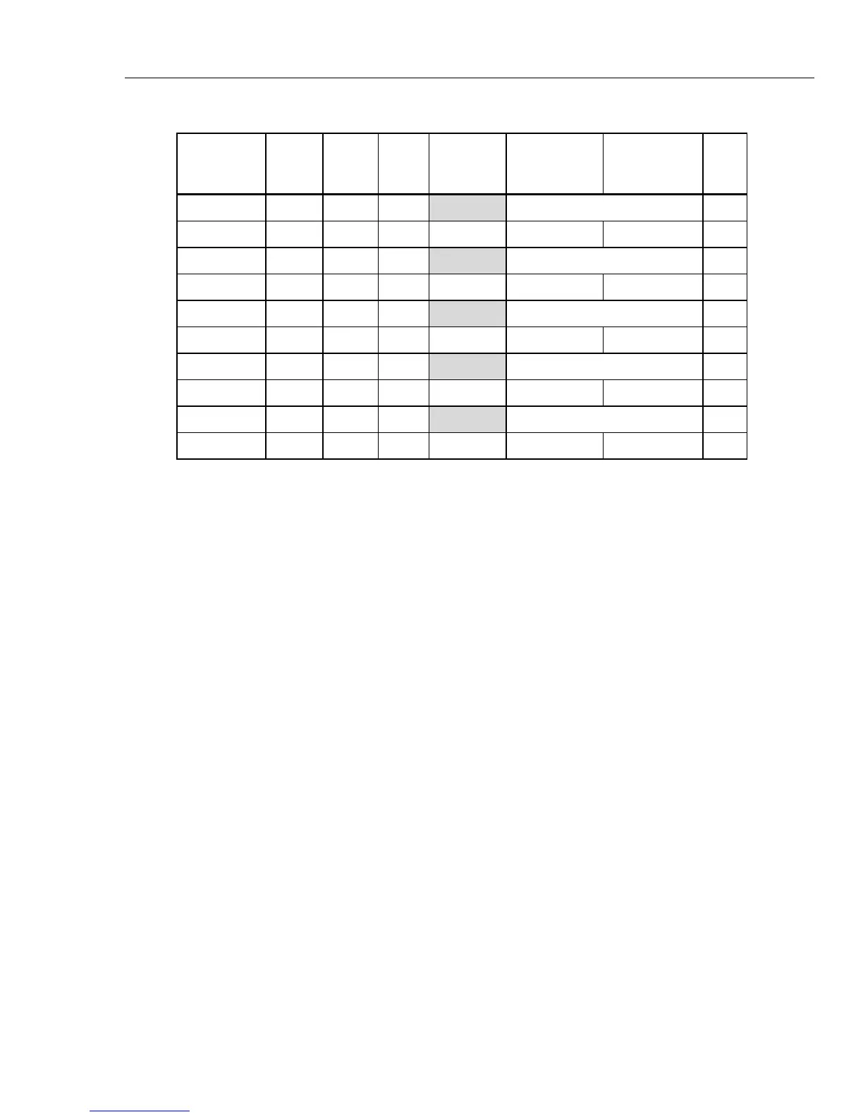
Table 5-4. 20 Amp Range Verification Points (cont.)
5720A
Output
8508A
ACV
filter
8508A
Input
A40B
Measured
Error (%)
Product
Specification
(99 %)
Measurement
uncertainty
(99 %)
TUR
0.8 V, 300 Hz 100 Rear 20 A - Reference level
2 V, 300 Hz 100 Front 20 A ±0.0900 % ±0.0057 % 16:1
0.8 V, 1 kHz 100 Rear 20 A - Reference level
2 V, 1 kHz 100 Front 20 A ±0.1600 % ±0.0057 % >25:1
0.8 V, 3 kHz 100 Rear 20 A - Reference level
2 V, 3 kHz 100 Front 20 A ±0.5000 % ±0.0068 % >25:1
0.8 V, 6 kHz 100 Rear 20 A - Reference level
2 V, 6 kHz 100 Front 20 A ±1.4000 % ±0.0068 % >25:1
0.8 V, 10 kHz 100 Rear 20 A - Reference level
2 V, 10 kHz 100 Front 20 A ±3.6000 % ±0.0068 % >25:1
120 Amp Range Verification
1. Push S on the Product and 5720A.
2. Connect the 100 A shunt between the output of the Product and the DMM front
input.
3. Push D on the Product.
4. Set the 5720A output to +0.6 V dc.
5. Set the DMM to front input.
6. Set the 5720A output to +0.6 V dc.
7. Set the DMM ‘m’ store to the 100 A shunt correction factor.
8. Set the DMM ‘-c’ and ‘÷z’ stores to 0.6.
9. Turn on the ‘*m’, ‘-c’ and ‘÷z’, and % math functions on the DMM.
10. Let the measurement become stable for a minimum of one minute and then record the
measured error in Table 5-5.
11. Set the DMM ‘-c’ and ‘÷z’ stores to -0.6.
12. Set the 5720A output to -0.6 V dc and record the measured error.
13. Set the DMM ‘-c’ and ‘÷z’ stores to 0.8.
14. Turn on the ‘*m’, ‘-c’ and ‘÷z’, and % math functions on the DMM.
15. Set the 5720A output to the values in Table 5-5 for the +1 V dc and -1 V dc
verification points.
16. Set the DMM ‘-c’ and ‘÷z’ stores to -0.8 for the -1 volt measurement.
17. Record the measured errors.
18. Set the 5720A output to the values in Table 5-5 for all the ac voltage verification
points and record the measured error. Use the transfer method for all ac
measurements.
For each ac measurement in Table 5-5: