52120A
Operators Manual
2-14
HIGH CURRENT
OUTPUT
LOW CURRENT
OUTPUT
850V PK
MAX
850V PK
MAX
30A PK
7V PK
MAX
180A PK
7V PK
MAX
OPTION
POWER
OUTPUT
(12V DC)
HI
LO
HI
LO
HIGH CURRENT
OUTPUT
LOW CURRENT
OUTPUT
850V PK
MAX
850V PK
MAX
30A PK
7V PK
MAX
180A PK
7V PK
MAX
OPTION
POWER
OUTPUT
(12V DC)
HI
LO
HI
LO
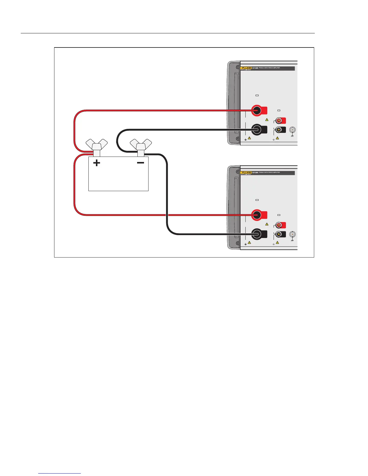
Fluke 52120A #1
Load
Fluke 52120A #2
gpp009.eps
Figure 2-6. Two Amplifier Outputs Connected in Parallel
Closed-Loop Operation
When better load regulation and phase-angle control is necessary, connect the Product in
a closed-loop configuration with a 6105A or 6100B. Through the feedback loop, the
6105A senses signal phase angle and amplitude to adjust the output and supply a more
accurate current signal.
To connect the feedback circuit, connect one end of the control cable to the Control Input
connector on the rear panel of the Product. Connect the other end of the cable to the
Current Amplifier Control Output connector on the rear panel of the 6105A or 6100B.
See Figure 2-7.
Remove all front-panel connections between the 6105A or 6100B and the Product. Turn
off and then turn on the 6105A or 6100B to initialize the analogue and control
connections between the instruments. The status indicators of the Product will show slave
mode operation. See Figure 2-3. The 6105A or 6100B will have three more current
ranges: 1 x Ext.2A, 1 x Ext.20A, and 1 x Ext.120A. The output terminals of the Product
are set through the 6105A or 6100B Front Panel Terminal Configuration screen. All the
keys but the STBY key are turned off on the Product.