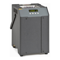
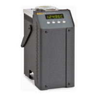
Micro-Bath
Temperature Display Hold
25
Mode Setting
The hold function is always in the automatic mode. In this mode the normal position is set to whatever
the switch position is when the set-point is changed. For example, if the switch is currently open when
the set-point is changed, the closed position then becomes the new active position. The normal
position will be set automatically under any of these conditions:
• a new set-point number is selected
• the set-point value is changed
• a new set-point is set through the communications channels
Switch Wiring
The thermal switch or cut-out is wired to the calibrator at the two terminals on the back of the Product
labeled DISPLAY HOLD. The switch wires can be connected to the terminals either way. Internally, the
black terminal connects to ground. The red terminal connects to +5 V through a 100 k
Ω resistor. The
calibrator measures the voltage at the red terminal and interprets +5 V as open and 0 V as closed.
Switch Test Example
This section describes a possible application for the temperature hold feature and how the instrument
is set up and operated.
Suppose you have a thermal switch which is supposed to open at about 75 °C (167 °F) and close at
about 50 °C (122 °F) and you want to test the switch to see how accurate and repeatable it is. You can
use the temperature hold feature and the scan function to test the switch. To make measurements,
observe the display or, preferably, collect data with a computer connected to the RS-232 port.
To set up the test:
1. Connect the switch wires to the terminals on the back of the Product and place the switch in the
well.
2. Enable set-point scanning by setting the scan to ON in the primary menu (see Scan Control).
3. Set the scan rate to a low value, say 1.0 °C/min. (see Scan Rate). If the scan rate is too high, you
may lose accuracy because of transient temperature gradients. If the scan rate is too low, the
duration of the test may be longer than is necessary. Experiment to find the best scan rate.
4. Set the first program set-point to a value above the expected upper switch temperature, for
example, 90 °C (194 °F).
5. Set the second program set-point to a value below the expected lower switch temperature, for
example, 40 °C (104 °F), in the program menu.
6. Collect data on a computer connected to the RS-232 port. Refer to Serial Interface Parameters, for
instructions to configure the RS-232 communications interface.